
System and method for extracorporeal temperature control

a technology of extracorporeal blood and temperature control, which is applied in the field of systems and methods for use in extracorporeal blood temperature control and patient temperature control, can solve the problems of limiting neurological damage, taking hours to reach the maximum level of brain damage resulting from stroke, etc., and achieves rapid systemic cooling of patients, induce hypothermia, and facilitate rapid initiation

Active Publication Date: 2017-08-31
MEDIVANCE
View PDF4 Cites 3 Cited by
  • Summary
  • Abstract
  • Description
  • Claims
  • Application Information

AI Technical Summary

Benefits of technology

The patent describes a system for rapidly cooling the blood in a patient to protect the brain and heart during procedures that may cause brain or heart damage. The system uses a special catheter with multiple lumens to connect to the patient's blood flow lines and a fluid pump to circulate cooling fluid through a heat exchanger. This allows the blood to be cooled quickly, reducing the risk of damage to the organs. The system can achieve a cooling rate of at least 4°C per hour and can be used with multi-lumen catheters for more efficient cooling.

Problems solved by technology

In that regard, stroke is a major cause of neurological disability, but research has established that even though a stroke victim's brain cells may lose their ability to function during the stroke, they do not necessarily die quickly.
Brain damage resulting from a stroke may take hours to reach a maximum level.
Again, rapid cooling of such patients may limit neurological damage.

Method used


Image

  • System and method for extracorporeal temperature control
  • System and method for extracorporeal temperature control
  • System and method for extracorporeal temperature control

Examples


Embodiment Construction

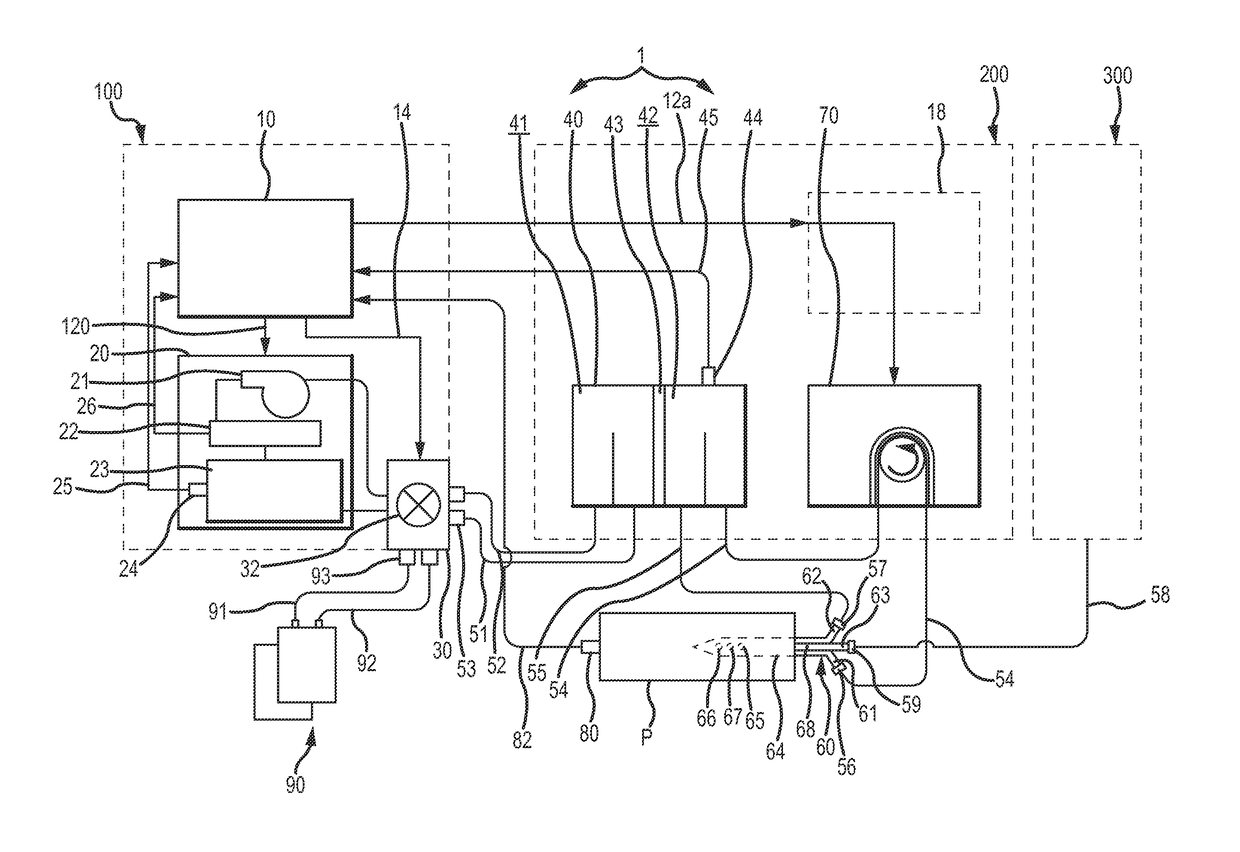
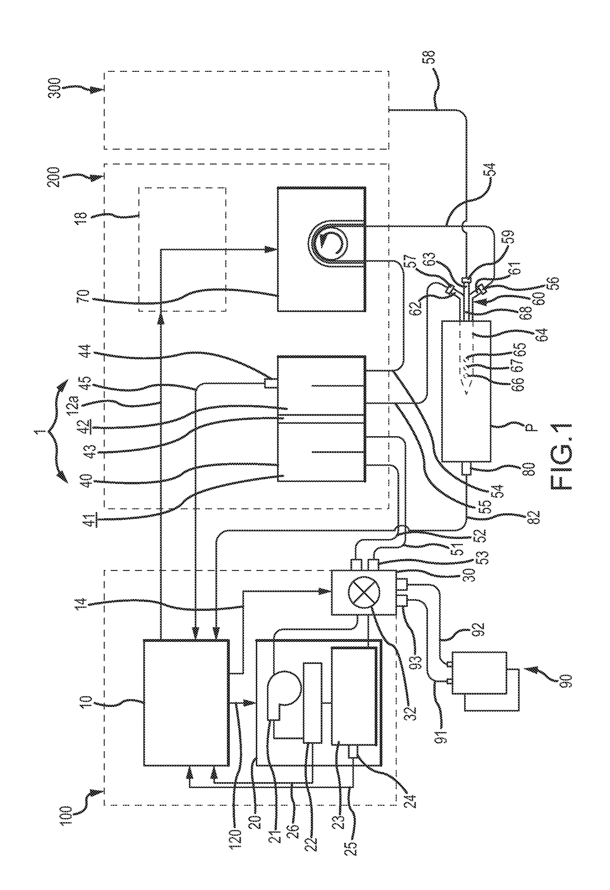
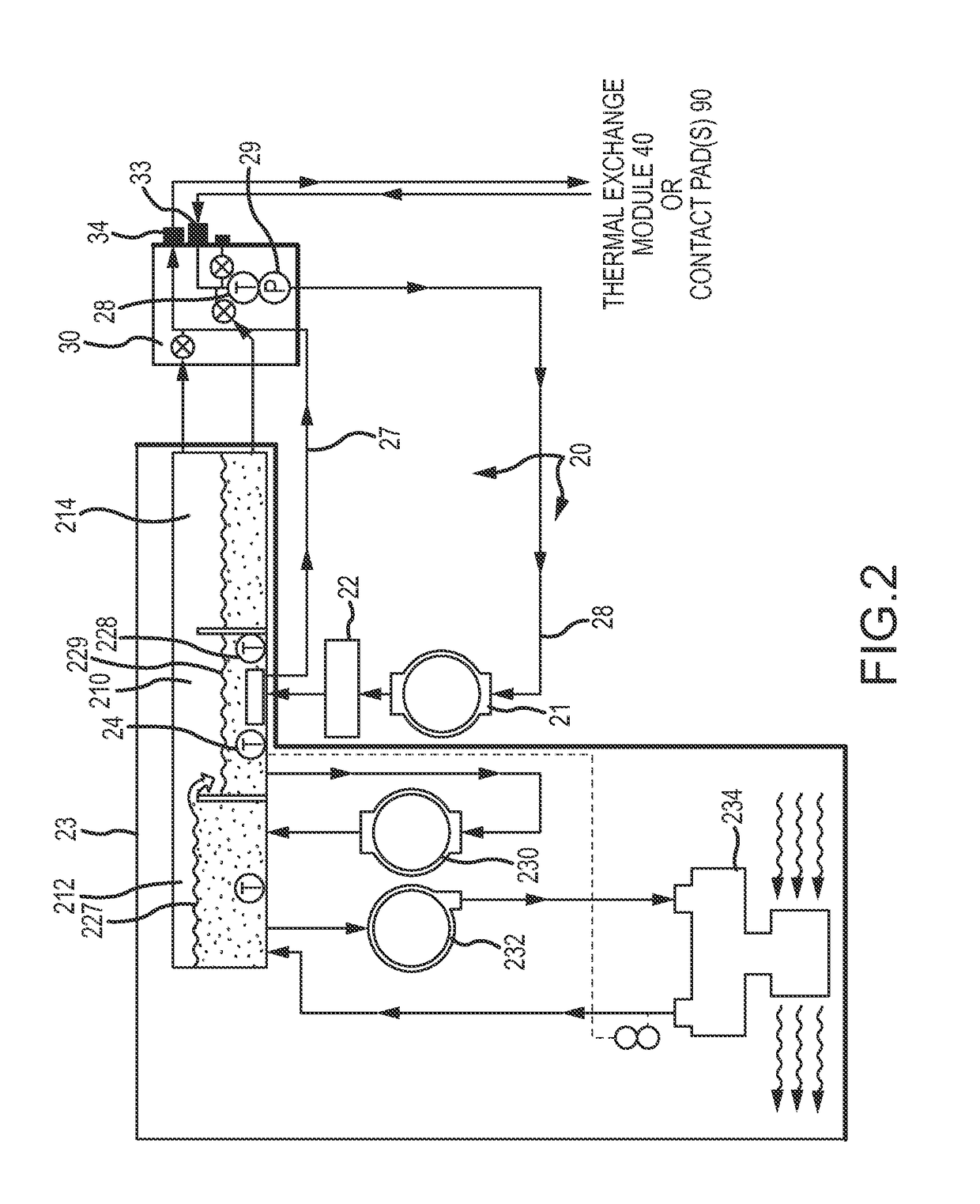
[0056]FIG. 1 schematically illustrates one embodiment of a system 1 for extracorporeal blood temperature control and patient temperature control. The system 1 includes a controller 10 for providing output signals for use in the operation of a fluid conditioning assembly 20 so as to cool, optionally warm, and circulate fluid through a thermal exchange module 40. In turn, the fluid conditioning assembly may include a fluid pump 21 for circulating the fluid to a heat exchanger 23 for passage to a fluid coupling interface 30. In one implementation, the controller 10, fluid conditioning assembly 20, and fluid coupling interface 30 may be supportably interconnected to a first support structure 100.

[0057]A first fluid circulation line 51 (e.g., a length of flexible tubing) and a second fluid circulation line 52 (e.g., a length of flexible tubing) may each be fluidly interconnected at one end to the fluid coupling interface 30 and may each be fluidly interconnected at another end to the the...


PUM


Abstract

Improved systems and methods for extracorporeal blood temperature control and patient temperature control, e.g., for induced hypothermia and optional normothermia, may include or otherwise employ a heat exchanger for cooling / warming of a fluid, a thermal exchange module having fluidly isolated first and second volumes, and a fluid pump for circulating the fluid through the heat exchanger and the first volume of the thermal exchange module. A blood pump may be provided for the flow of blood through the second volume of the thermal exchange module, and a first controller may be provided for providing output signals for use in operation of the heat exchanger to selectively control thermal exchange between the fluid circulated through the first volume of the thermal exchange module and the blood flowed through the second volume of the thermal exchange module, thereby providing for selective cooling / warming of the blood. A multi lumen catheter may be utilized for the flow of blood from a patient vascular system to the second volume of the thermal exchange module, and for flow of blood from the second volume of the thermal exchange module back to the patient vascular system. The circulated fluid may be optionally circulated through a patient contact pad(s) for contact cooling / warming, wherein patient cooling / warming may be provided in a first mode via blood cooling / warming in the thermal exchange module, and patient cooling / warming may be provided in a second mode via thermal exchange by the contact pad(s).

Description

RELATED APPLICATIONS[0001]This application claims priority to U.S. Patent Application No. 62 / 037,437, filed Aug. 14, 2014, entitled “SYSTEM AND METHOD FOR EXTRACORPOREAL TEMPERATURE CONTROL,” which application is incorporated herein by reference in its entirety.FIELD OF THE INVENTION[0002]The present invention relates to systems and methods for use in extracorporeal blood temperature control and patient temperature control, and in particular, for therapeutic patient temperature cooling to induce hypothermia and optionally patient warming to achieve normothermia.BACKGROUND OF THE INVENTION[0003]There are a number of medical conditions for which systemic cooling is an effective therapy. For example, rapid systemic cooling of stroke, head-trauma, cardiac arrest, and myocardial infarction patients has significant therapeutic benefits.[0004]In that regard, stroke is a major cause of neurological disability, but research has established that even though a stroke victim's brain cells may l...

Claims


Application Information

Patent Timeline
Patent Type & Authority Applications(United States)
IPC IPC(8): A61M1/36A61F7/00A61M5/00A61M25/00A61M5/14A61F7/12A61M1/10A61M60/113A61M60/268A61M60/515A61M60/538A61M60/857
CPCA61M1/369A61F7/12A61F7/0085A61M1/10A61M25/0026A61F2007/0096A61M5/007A61F2007/0056A61F2007/126A61F2007/0086A61M5/14A61M19/00A61M2205/3368A61M2205/3355A61M60/857A61M60/268A61M60/113A61M60/538A61M60/515
Inventor VOORHEES, MARC E.PARK, CHRISTOPHERPRIVITERA, SALVATORE
Owner MEDIVANCE
Learn More