A method and device for concentrating particles in a fluid sample

a technology of fluid sample and concentrating device, which is applied in the direction of transportation and packaging, laboratory glassware, instruments, etc., can solve the problems of filtration unit blockage, achieve the effect of improving the recovery rate, concentration ratio and overall efficiency of the whole process, and preventing the agglomeration of particles and/or attachmen

Inactive Publication Date: 2017-08-31
WATER OPTICS TECH
View PDF1 Cites 1 Cited by
  • Summary
  • Abstract
  • Description
  • Claims
  • Application Information

AI Technical Summary

Benefits of technology

[0013]By providing an acoustic transducer, acoustic waves can be generated to transmit energy to the fluid thereby agitating the fluid and particles at the sub-region to disperse the particles. This improves the recovery rate, concentration ratio and overall efficiency of the whole process. Firstly, the dispersal of the particles inhibits the filtration unit from being blocked. Secondly, at a time when the concentrated particles are to be extracted from the device (which is typically performed by creating a fluid flow from the second compartment to the first, a “backflush”), the acoustic waves detach the particles from the filtration unit.
[0014]Typically, the acoustic transducer is configured to generate acoustic waves in the sub-region to disperse the particles at a time when the fluid sample flows from the first compartment to the second compartment. This is advantageous since it would prevent the agglomeration of the particles and / or attachment of the particles to the filtering unit during the filtration / filtering process.

Problems solved by technology

Firstly, the dispersal of the particles inhibits the filtration unit from being blocked.
Secondly, at a time when the concentrated particles are to be extracted from the device (which is typically performed by creating a fluid flow from the second compartment to the first, a “backflush”), the acoustic waves detach the particles from the filtration unit.

Method used


Image

  • A method and device for concentrating particles in a fluid sample
  • A method and device for concentrating particles in a fluid sample
  • A method and device for concentrating particles in a fluid sample

Examples


examples

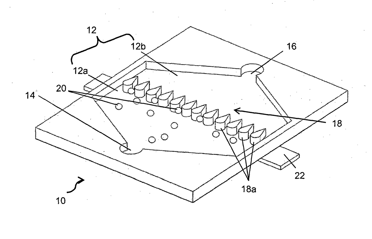
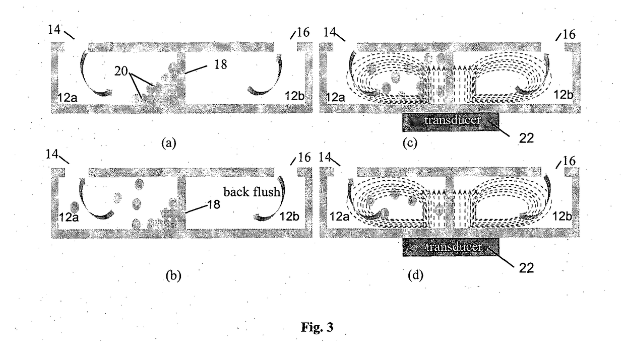
[0070]To perform preconcentration of a water sample using the device 100, 100 C. parvum oocysts are suspended in 10 L tap water and injected into the first stage chambers 112, 212, 312, 412, 512, 612, 712, 812 using a peristaltic pump (Masterflex, USA) with a flow rate of 500 mL / min. After 20 mins, all samples flow through the first stage chambers 112, 212, 312, 412, 512, 612, 712; 812 then the pump reverses its rotational direction and generates the backflush flow with a flow rate of 20 mL / min. The blocked particles are flushed out and collected from the inlets 114 of the first stage chambers 112, 212, 213, 412, 512, 612, 712, 812. The sample is concentrated into 25 mL after the first stage concentration. Thereafter, the concentrated sample is injected into the second stage chamber 912 with a flow rate of 5 mL / min. After further round of concentration in the second stage chamber 912, the sample volume is reduced into 0.2 mL.

[0071]In the above example, the parallel first stage chamb...


PUM

PropertyMeasurementUnit
pore sizeaaaaaaaaaa
sizeaaaaaaaaaa
porosityaaaaaaaaaa

Abstract

A microfluidic device and method is provided for concentrating particles in a fluid sample. The microfluidic device has a chamber, wherein the chamber has a filtering unit defining a first compartment and a second compartment, the first compartment being in fluid communication with the second compartment and being for receiving a fluid sample containing particles, the filtering unit being configured to selectively retain particles of the fluid sample based on a size of the particles, at a sub-region of the first compartment as the fluid sample flows from the first compartment to the second compartment; and an acoustic transducer configured to generate acoustic waves in the sub-region to disperse the particles.

Description

FIELD OF INVENTION[0001]The invention relates to a method and device for concentrating particles in a fluid sample, and in particular, to a method and device for filtering and concentrating particles of interest in a fluid sample.BACKGROUND[0002]There is a wide range of microbial species in drinking water that cause fatal outbreaks, including viruses, bacteria, protozoa and other particulates [1]. A fundamental limiting factor in the detection and quantification of these microorganism particles in drinking water is the very small number of each organism present and the interference between these microbial species. Therefore, in most detection techniques, preconcentration and filtration are essential prior to detection and quantification. A preconcentrator is a device which collects target samples (typically particles) from a fluid and ejects them on command to the next stage of treatment (e.g. detection and analysis) at a much higher concentration.[0003]A consequence of this multi-s...

Claims


Application Information

Patent Timeline
Patent Type & Authority Applications(United States)
IPC IPC(8): B01L3/00B01F15/00B01F11/02G01N1/40B01F13/00
CPCB01L3/50273B01L3/502761G01N1/4077B01F13/0059B01F11/0266B01F2215/0037B01L2400/0436B01L2200/0652B01L2400/086B01F2215/0073B01F2215/0052B01F15/0098G01N2015/0088B01L3/502753B01L2300/0816B01L2400/0487B01F31/86B01F33/30B01F35/1872B01F2101/23B01F2101/44B01F2101/305
Inventor LIU, AI QUNLEI, LEIPUKKEYIL SHAMSUDDIN, SHAHNAWAZ
Owner WATER OPTICS TECH
Why Eureka
Try Eureka