
Flying apparatus

a technology of flying apparatus and propeller, which is applied in the direction of machines/engines, vertical landing/take-off aircraft, transportation and packaging, etc., can solve the problems of long runways, unstable flight, and the most difficult maneuvers of airplanes

Active Publication Date: 2017-08-31
TWINGTEC +1
View PDF7 Cites 16 Cited by
  • Summary
  • Abstract
  • Description
  • Claims
  • Application Information

AI Technical Summary

Benefits of technology

The invention is a flying device that can take off and land in windy conditions without needing a runway. It has good control when in the air and can safely land on a target.

Problems solved by technology

Launching and landing are typically the most difficult maneuvers for an airplane.
As a consequence, long runways are needed.
The problem with these airplanes, however, is that the flight can get unstable with fast changing winds.
Furthermore, structural elements with considerable complexity are needed to connect the propellers with the airplane.
The situation is even more complex when flying apparatuses, such as kites, are considered that are connected to the ground by means of tethers.
A limitation of this method is that the wind interferes with the flying apparatus in a destructive way in this hover position.
In fact the main wing is with respect to the wind in a stalled position which makes the flying apparatus difficult to stabilize.
Furthermore, the transitions from forward flight mode into the vertical hover mode and vice versa are rather delicate manoeuvers which are not easy to accomplish.
On the other hand, due to the constraints of the tethers, conventional launching and landing procedures of an airplane with a runway cannot be applied.
Safe and efficient as well as fully autonomous launching and landing of the flying apparatus from and to a defined location is one of the main challenges to make kitepower technology economically available.
While vertical launching and landing can easily be achieved with this concept, the power production is not efficient.
This considerably reduces the amount of electrical power production.
Further, the system cannot operate in a crosswind mode which again limits the efficiency very much.
However, the device cannot operate in a forward flight mode and thus cannot operate in a crosswind mode.
Thus, it is not very efficient.
Furthermore, the device has a rather complex construction with a lot of adjustable and rotating parts resulting in high costs and reduced life time.

Method used


Image

  • Flying apparatus
  • Flying apparatus
  • Flying apparatus

Examples


Embodiment Construction

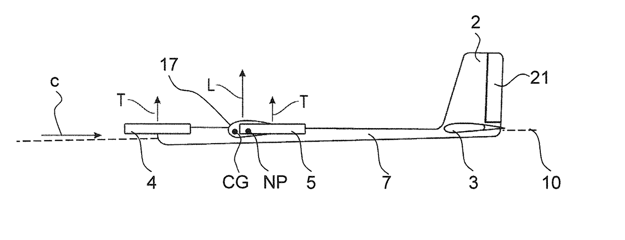
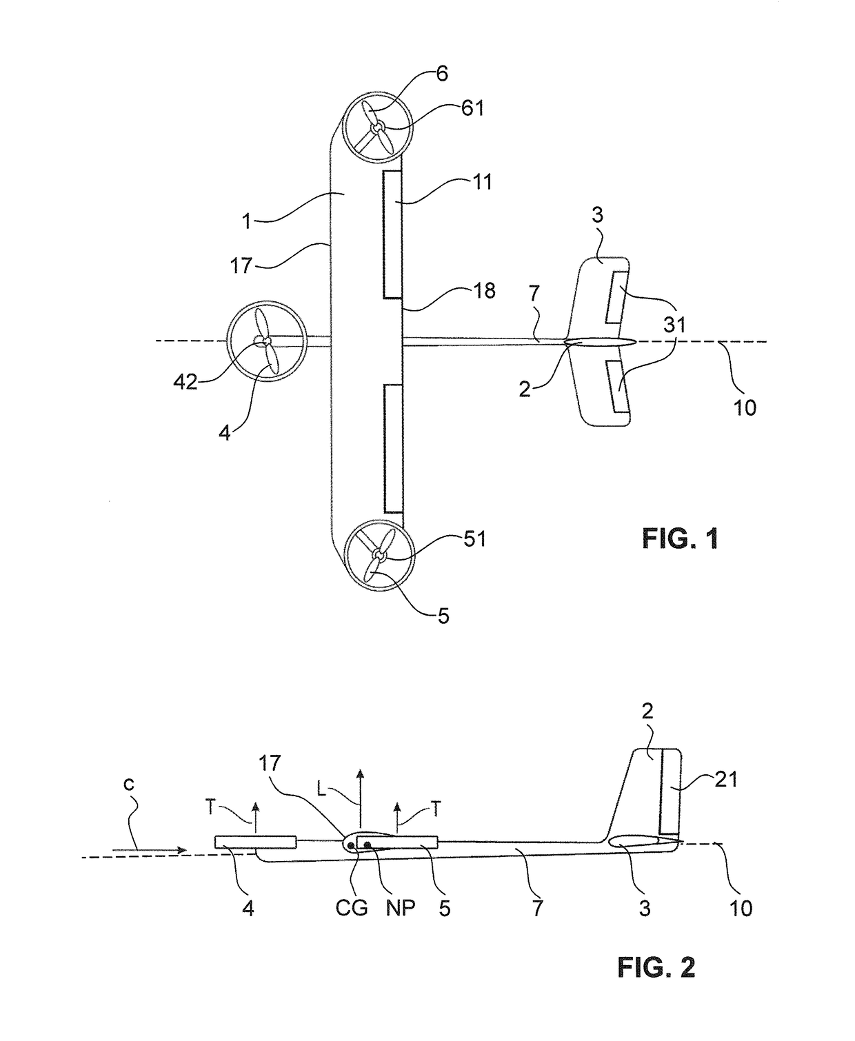
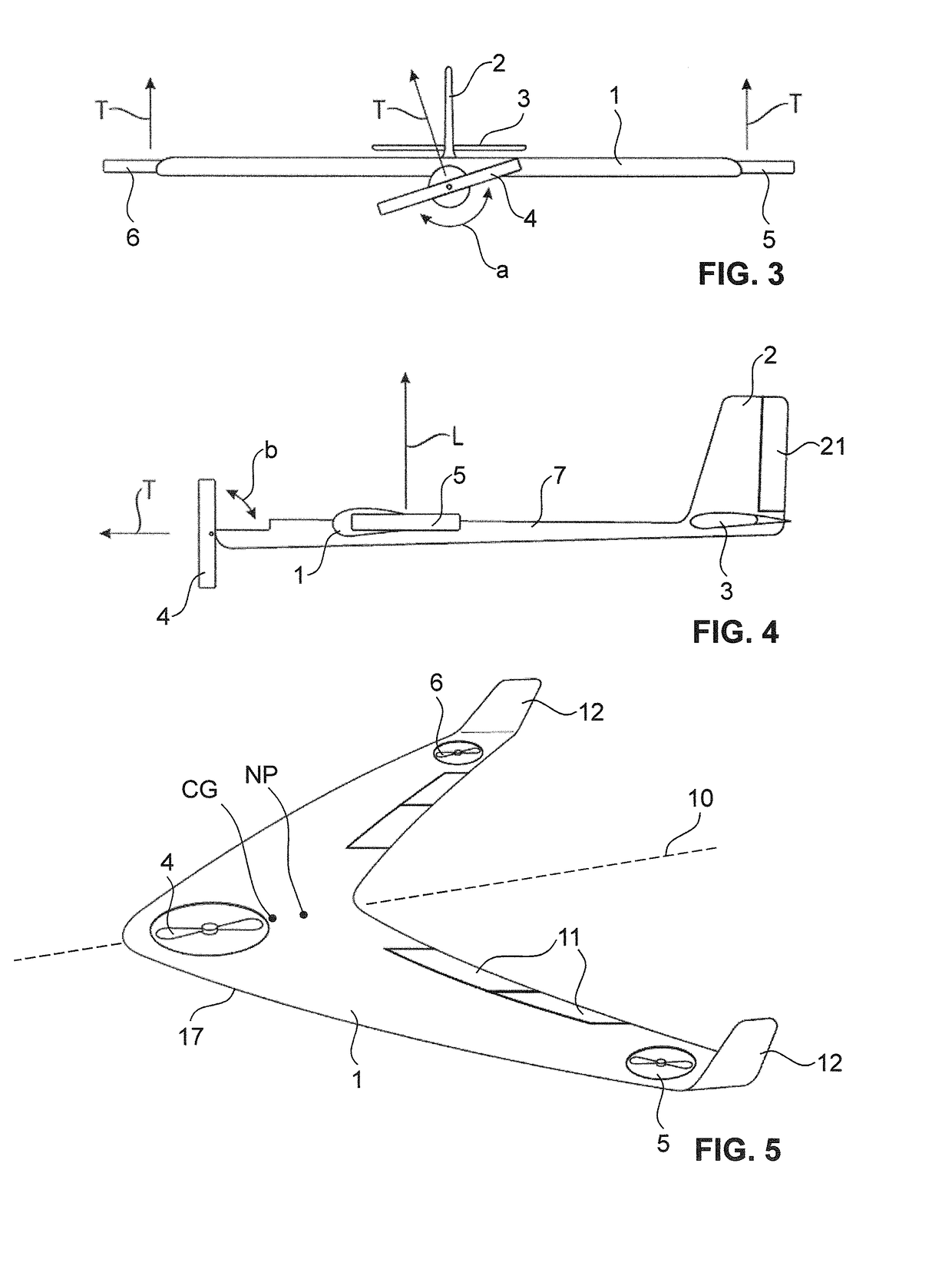
[0053]FIGS. 1 to 8 show several embodiments of flying apparatuses according to the invention. FIGS. 9a to 9c show, how a flying apparatus according to the invention can be used to harness wind energy in a system for generating electrical energy. FIG. 10 shows a further application of the flying apparatus according to the invention as a stationary elevated platform. To each of the embodiments as shown in FIGS. 1 to 8 one or several tethers can be attached, in order to use the respective flying apparatus for the generation of electrical energy or as a stationary elevated platform. Electrical energy and or communication signals can be transmitted from the ground to the flying apparatus or vice versa by means of the tether(s), which in this case is / are electrically conductive and / or comprise communication means, such as a fibre optical cable.

[0054]Elements having an identical or similar function are indicated by the same reference numerals throughout all embodiments as shown in FIGS. 1 ...


PUM


Abstract

A flying apparatus is provided that comprises a airfoil (1) with a streamlined profile for generating an aerodynamic lift force vector (L) acting on the flying apparatus when being exposed to an apparent air flow. The flying apparatus also comprises at least three drive units (4, 42; 5, 51; 6, 61) being adapted to generate a resulting thrust force vector acting on the flying apparatus, the thrust force vector being alignable essentially in parallel with the aerodynamic lift force vector (L). For controlling the aerodynamic pitch of the flying apparatus, the flying apparatus comprises at least one control surface (31, 11). Furthermore, the flying apparatus has an aerodynamic neutral point (NP) that lies, along the longitudinal centre axis (10) and in the direction from the leading edge (17) to the trailing edge (18) of the airfoil (1), behind the centre of gravity (CG) of the flying apparatus.

Description

TECHNICAL FIELD[0001]The present invention concerns a flying apparatus, in particular a flying apparatus for generating electrical energy.PRIOR ART[0002]Launching and landing are typically the most difficult maneuvers for an airplane. In order to maintain a minimal lift force to counterbalance the weight, the speed of the airplane should not drop below some threshold value. As a consequence, long runways are needed.[0003]In documents WO 03 / 029075 A2 and WO 2010 / 137016 A2, it is proposed to provide propellers that are able to generate a vertically oriented thrust, in order to enable vertical launching and landing as well as hovering of the airplane. The problem with these airplanes, however, is that the flight can get unstable with fast changing winds. Furthermore, structural elements with considerable complexity are needed to connect the propellers with the airplane.[0004]The situation is even more complex when flying apparatuses, such as kites, are considered that are connected to ...

Claims


Application Information

Patent Timeline
IPC IPC(8): F03D9/32B64C39/02B64F3/02B64C29/00
CPCF03D9/32B64C29/0033B64C2201/021B64C39/024B64F3/02B64C39/022B64U10/25B64U2101/10B64U40/10B64U30/297B64U30/293B64U10/60F03D5/00Y02E10/70
Inventor LUCHSINGER, ROLFGOHL, FLAVIO
Owner TWINGTEC
Learn More