Cross-flow wave making pump

a wave making pump and cross-flow technology, applied in wave producing pumps, liquid fuel engines, machines/engines, etc., can solve the problems of insufficient liquid circulation, unfavorable wave production, and dead zones, and achieve the effect of reducing the dead zone where the liquid flows extremely slowly and high torqu

Active Publication Date: 2017-08-31
GUANGZHOU MAIGUANG ELECTRONIC TECHNOLOGY CO LTD
View PDF6 Cites 3 Cited by
  • Summary
  • Abstract
  • Description
  • Claims
  • Application Information

AI Technical Summary

Benefits of technology

[0018]The cross-flow wave making pump of the present invention drives the impeller assembly pivotally connected to the two ends of the impeller shell by the motor, so as to force the liquid to circulate, wherein the impeller assembly comprises the impeller used for driving a liquid flow, the first turntable and the second turntable respectively fixed at the two ends of the impeller, wherein the first turntable is provided with the shaft rotatably mounted in the impeller shell, the second turntable is provided with the cavity used for receiving the rotor shaft of the motor. By rotating the impeller assembly, the cross-flow wave making pump of the present invention creates a sufficient liquid-circulation in the container, which significantly reduces the dead zone where the liquid flows extremely slowly; furthermore, the cross-flow wave making pump has two impeller assemblies and two impeller shells, each side of the motor is provided with one impeller assembly and one impeller shell, in this way, the cross-flow wave making pump of the present invention makes a further contribution to the liquid-circulation. In addition, the motor is an outer rotor motor, such that the impeller assemblies can obtain a relatively high torque. Therefore, the motor can drive a big-sized strip-shaped impeller so as to overcome the defect that the torque of an inner motor brushless motor is relatively small.

Problems solved by technology

The inner rotor brushless motor is characterized by high rotation speed but low torque, so it can only drive small-sized vanes, moreover, the outlet area of this kind of wave making pumps is relatively small, when a high flow velocity is required, it needs to increase the rotation speed to increase the flow rate.
Therefore, when this kind of wave making pump is applied to making liquid circulation or making waves, it's likely to cause uneven flow or insufficient liquid-circulation, and form, in the container, dead zones where the liquid flows extremely slowly.

Method used


Image

  • Cross-flow wave making pump
  • Cross-flow wave making pump
  • Cross-flow wave making pump

Examples


Embodiment Construction

[0065]Varied embodiments will now be described with reference to the figures.

[0066]Pumping systems in aquarium tanks and containers provide a number of key functions, including moving water and / or debris to or from the tank filtration systems, creating currents within the tank for fish, assisting with draining and / or filling of the tank, oxygenating the water, maintaining an even water temperature throughout the tank, and / or promoting beneficial bacteria growth throughout the tank. Sufficient water circulation through the tank is integral to these functions. Traditional water pumps rely on high flow velocity and high hydraulic head, thereby requiring particular positioning within the tank (e.g., at a sufficient depth within the tank to achieve the requisite hydraulic head), which oftentimes results in proper circulation only within certain portions of the tank, leaving dead zones where the water flows extremely slowly.

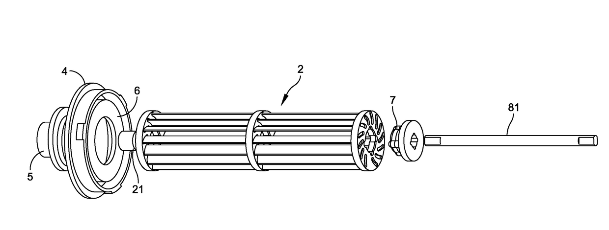
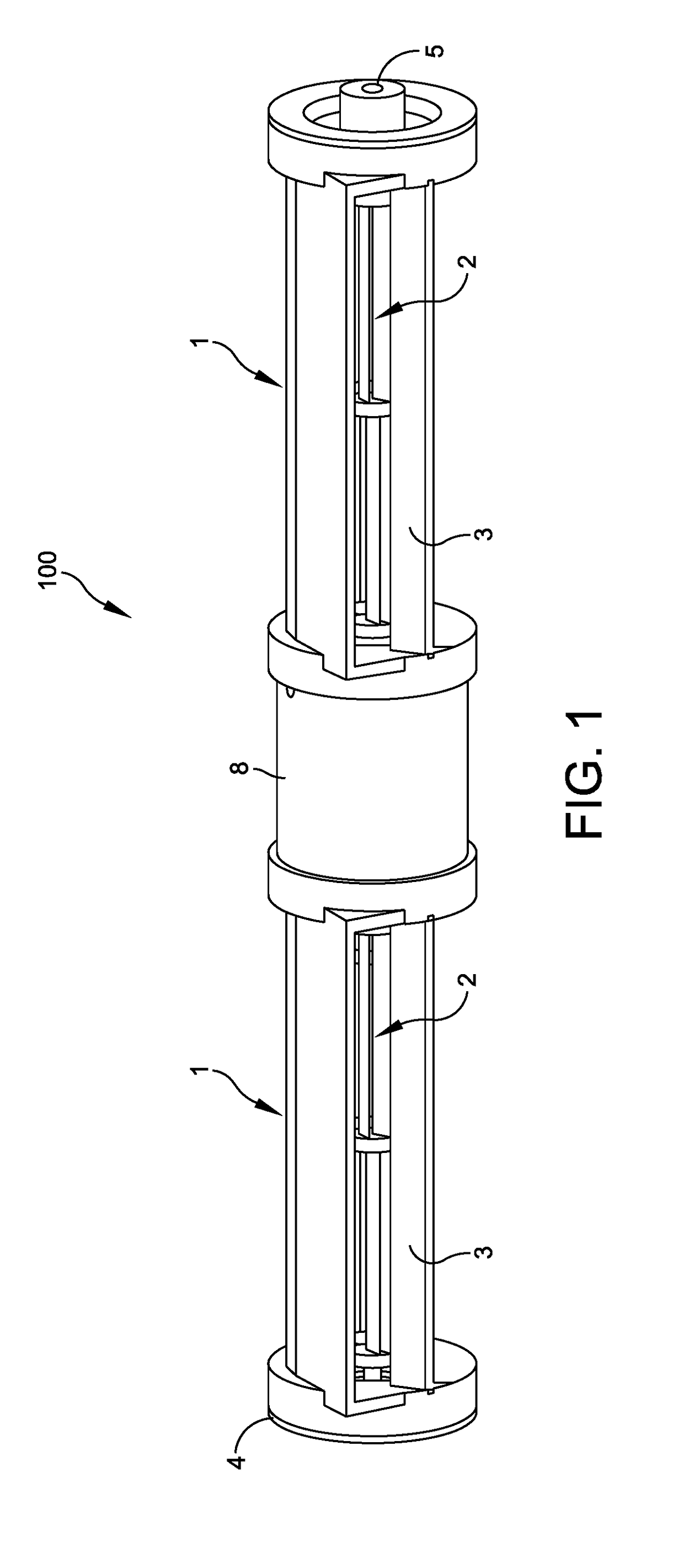
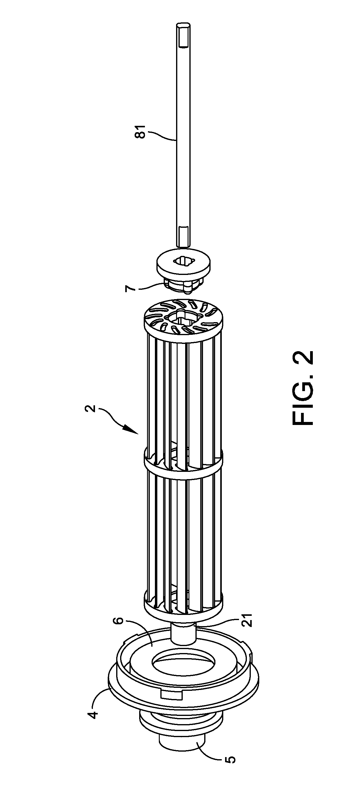
[0067]Embodiments of the cross-flow wave making pump discussed he...


PUM


Abstract

This invention relates to a cross-flow wave making pump comprising an impeller shell forming a water intake and a water outlet, an impeller assembly pivotally connected to two ends of the impeller shell, and a motor used for driving the impeller assembly; wherein, the impeller assembly comprises an impeller used for driving a liquid flow, a first turntable and a second turntable respectively fixed at two ends of the impeller, wherein the first turntable is provided with a shaft rotatably mounted in the impeller shell, the second turntable is provided with a cavity used for receiving a rotor shaft of the motor. The embodiments of the present invention can provide a sufficient liquid-circulation in a container, and significantly reduce the dead zone where the liquid flows extremely slowly. Other embodiments are disclosed.

Description

REFERENCE TO PENDING PRIOR PATENT APPLICATIONS[0001]This patent application is a continuation-in-part of pending prior U.S. patent application Ser. No. 14 / 358,739, filed Apr. 11, 2014 by Weixin Liang for CROSS-FLOW WAVE MAKING PUMP, which is a National Stage Entry of International Application No. PCT / CN2014 / 075205, filed Apr. 11, 2014 by Weixin Liang for CROSSFLOW-TYPE FLOW PUMP, which in turn claims priority to Chinese Application No. 201420159547.1, filed Apr. 2, 2014 by Weixin Liang, all of which patent applications are hereby incorporated herein by reference.FIELD OF THE INVENTION[0002]This invention relates to a wave making pump, especially to a cross-flow wave making pump that can provide a sufficient liquid-circulation in a container.BACKGROUND OF THE INVENTION[0003]In most cases, existing wave making pumps use inner rotor brushless motor with propeller-type axial vanes to drive a liquid flow, or use inner rotor brushless motor with centrifugal vanes to swallow and extrude li...

Claims


Application Information

Patent Timeline
Patent Type & Authority Applications(United States)
IPC IPC(8): F04D13/06F04D17/04F04D29/44F04D29/22F04D29/42F04D1/12F04D29/043
CPCF04D13/06F04D1/12F04D17/04F04D29/445F04D29/22F04D29/4293F04D29/043F04D1/00F04D1/02F04D13/086F04D29/20F04D35/00
Inventor LIANG, WEIXIN
Owner GUANGZHOU MAIGUANG ELECTRONIC TECHNOLOGY CO LTD
Why Eureka
Try Eureka