

Brake device
- Summary
- Abstract
- Description
- Claims
- Application Information
AI Technical Summary
Benefits of technology
Problems solved by technology
Method used
Image

Examples
Embodiment Construction
)
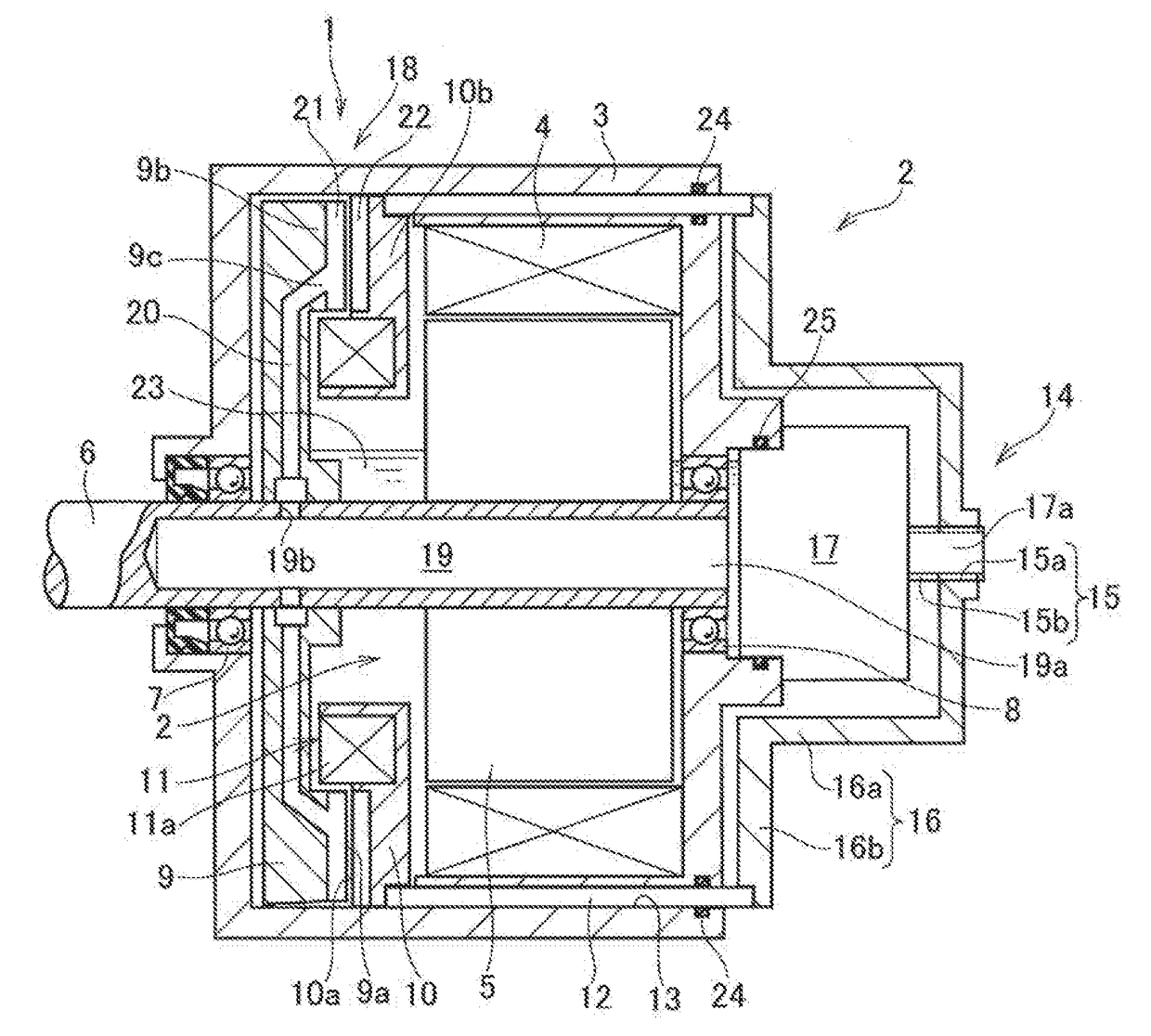
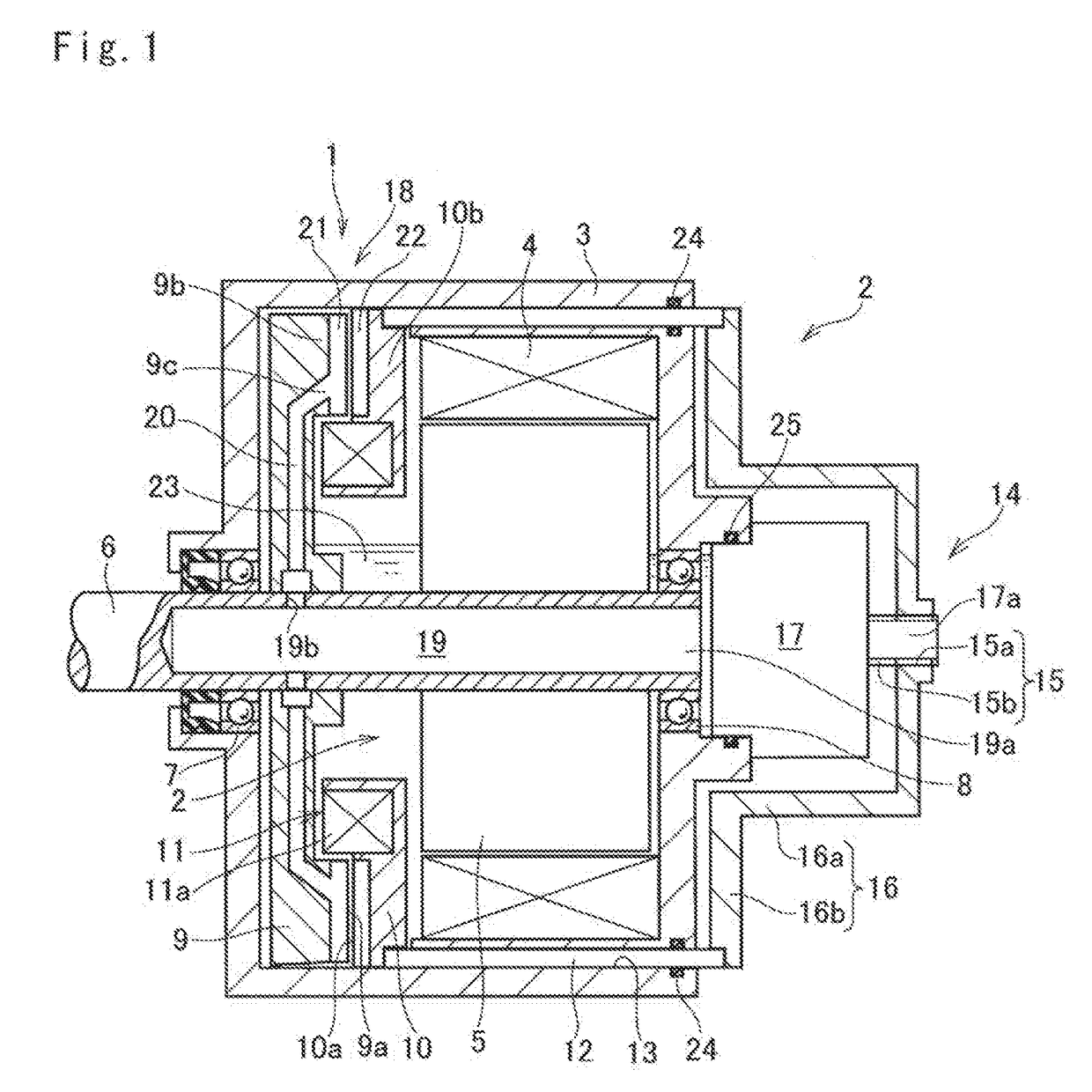
[0024]Preferred embodiment of the present application will now be explained with reference to the accompanying drawings. Referring now to FIG. 1, there is shown a brake device according to the preferred embodiment of the present application. As illustrated in FIG. 1, the brake device 1 and the motor 2 are held in a common casing 3.
[0025]The motor 2 is intended to be used as a prime mover of an automobile, and for example, a permanent magnet synchronous motor, and an induction motor may be used as the motor 2. Specifically, the motor 2 comprises a stator 4 that is fixed to an inner face of the casing 3, a motor shaft 6 as an output shaft of the motor 2 that is supported by bearings 7 and 8 in a rotatable manner at both ends of the casing 3, and a rotor 5 that is fitted onto the motor shaft 6 to be rotated integrally with the motor shaft 6 but relatively to the stator 4. One of end portions of the motor shaft 6 (of the left side in FIG. 1) protrudes from the casing 3, and the other e...
PUM
 Abstract
Description
Claims
Application Information