Low weight tube fin heat sink

a heat sink and low weight technology, applied in the field of low weight tube fin heat sinks, can solve the problems of large heat sink fin area, difficult to achieve affordable technologies, and need to remove heat, so as to achieve the same heat dissipation properties, improve thermal energy dissipation properties, and reduce weight

Inactive Publication Date: 2017-08-31
SIGNIFY HLDG BV
View PDF0 Cites 7 Cited by
  • Summary
  • Abstract
  • Description
  • Claims
  • Application Information

AI Technical Summary

Benefits of technology

[0009]Further, such cavity may in embodiments not necessarily have the same width(s) over the entire length of the cavity (i.e. the wall(s) of the pin-shaped fin may vary in thickness over the height). In line with this, the cavity is larger closer to the top part and smaller closer to the bottom part. This may add to the strength of the pin-shaped fin, which may especially be of relevance for longer fins.
[0010]It appears that such heat sink may have the same dissipation properties as conventional heat sinks, but at a much lower weight. In other words, at the same weight, much better thermal energy dissipation properties are obtained. This weight reduction may (thus) also be used to reduce the size of the heat sink while still maintaining suitable heat sink functionality. Further, such heat sink may also be used to improve the efficiency of the device, as in general efficiency decreases with increasing temperature. With the present heat sink, the functional element in a device, such as a light source, may be cooled better, leading to a more efficient operating of the device (such as the light source). Here, the term efficiency may especially relate to system efficacy (in 1 m / W) or system efficiency (in optical power / total power). For non-lighting device, other indications of efficiency may be used.

Problems solved by technology

With the current efficacies of the lighting systems a lot of heat needs to be removed and a lot of heat sink fin area is required for that.
Reduction to thin fins appears to be of interest but this may lead to dimensions which are very hard to achieve with affordable technologies.
Moreover, thin ribs of the heat sink appear to be more vulnerable to deformation and damage, especially when used in outdoor applications.
However, air flow obstruction by the tubular structures may be a limiting factor in the thermal performance.
The tubes may have low weight, such as due to low (fin) wall thickness and also a high bending and buckling stiffness due to the tubular shape.

Method used


Image

  • Low weight tube fin heat sink
  • Low weight tube fin heat sink
  • Low weight tube fin heat sink

Examples


Embodiment Construction

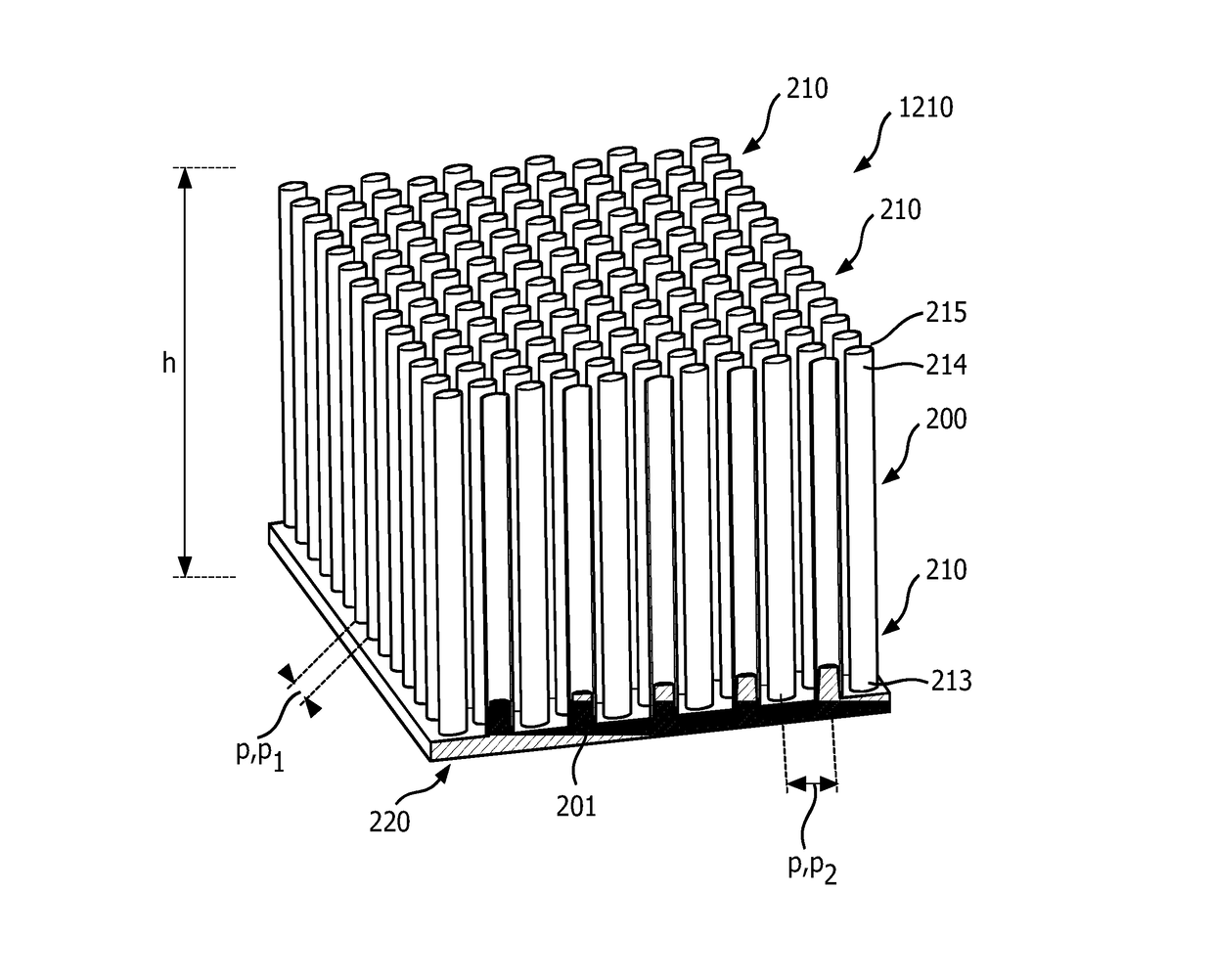
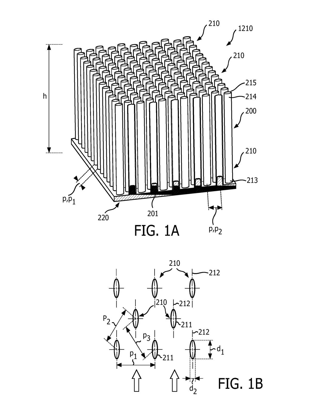
[0044]FIG. 1a schematically depicts a heat sink 200 comprising a plurality of pin-shaped fins 210 and a support 220. Both the fins and support may e.g. be of aluminum. The support 220 may especially be a plate-like element. The support may especially have a thickness (or height) in the range of 0.5-50 mm, such as in the range of 2-10 mm. The fins 210 are arranged at one side of the support 220. The other side of the support 220 may be in thermal contact with a functional element (see below).

[0045]Each fin 210 has a fin height h relative to the support 220, such as in the range of 1-100 cm. Further, each fin has a bottom part 213 associated with the support 220 and a top part 214. As is visible for the fins shown in cross-section, the pin-shaped fins 210 are hollow over 100% of their fin height h. Hence, the total height of the heat sink is the thickness or height of the support 220 and the height h of the fins 210.

[0046]Here, a regular array or pattern 1210 is shown. The fins 210 ha...


PUM


Abstract

The invention provides a lighting device comprising a light source and a heat sink (200). The heat sink (200) is configured to dissipate thermal energy from the light source when in operation. The heat sink comprises a plurality of pin-shaped fins (210) and a support (220), wherein each fin (210) has a fin height (h) relative to the support (220), a bottom part (213) associated with the support (220) and a top part (214), a cross-section having a first width (d1) and a second width (d2) having a ratio d1/d2 selected from the range of 1.2-10, and a first width axis, wherein the first width axes of the pin-shaped fins (210) are arranged parallel, and wherein the pin-shaped fins (210) are hollow over at least part of their fin height (h).

Description

FIELD OF THE INVENTION[0001]The invention relates to a lighting device including a heat sink. The invention further relates to a method of assembling a device, such as such lighting device. Yet, the invention also relates to the heat sink per se.BACKGROUND OF THE INVENTION[0002]The use of heat sinks for lighting applications is known in the art. US2014146544, for instance, describes a LED optical light engine spotlight which can accommodate a variable number of light-emitting diodes (LEDs). An optical projection lens mounted in front of the LEDs merges the separate LED beams into a single beam, similar to the single beam provided by a halogen light and reflector. A heat sink provides convection cooling up to approximately 100° F. An optional fan provides additional heat dissipation for more extreme conditions. An optional accessory lens provides additional capabilities, including flood lenses, colored lenses and rock guards, for example. The depicted device can be hard wired or wire...

Claims


Application Information

Patent Timeline
Patent Type & Authority Applications(United States)
IPC IPC(8): F28F3/02F21V29/80
CPCF21V29/80F28F3/022F21V29/81F21Y2115/10
Inventor KADIJK, SIMON EMEMIRSADEGHI, MOHAMMADGEHRELS, DIRK
Owner SIGNIFY HLDG BV
Why Eureka
Try Eureka