Test Equipment Interface

Inactive Publication Date: 2017-08-31
PLATO ELECTRONICS LLC
View PDF3 Cites 8 Cited by
  • Summary
  • Abstract
  • Description
  • Claims
  • Application Information

AI Technical Summary

Benefits of technology

[0017]In accordance with another object of the invention, the measurements can be audibly communicated to the user. For instance, the wearable device can audibly communicate any measurements. Alternatively, a pair of headphones that can communicate measurements may be associated with the wearable device. Alternatively still, the test equipment device could be configured to audibly communicate any measurements. Also, a pair of headphones could be connected to the test equipment device to communicate audible readings taken by the test equipment. Other speakers could be used with either the wearable device or the test equipment to audibly communicate readings and measurements to a user. As a result, the user can stay focused on what is being measured.
[0018]In accordance with another object of the invention, the test equipment device could be a wireless tool. Different criteria can be measured and stored relating to use of the wireless tool. For instance, the, test equipment device could be a wireless drill. While in use, criteria such as amount of use, time of use, and amount of load can be measured and stored. This would allow a user to anticipate when a given drill bit would likely become dull. Additionally, this would allow business owners such as contractors to monitor productivity of workers based on the amount of time a given tool is in use. Additionally, profiles can be set that establish maximum criteria values. For instance, the hand drill could automatically be powered off in the event that it experiences a significant load.

Problems solved by technology

A common problem with all of the equipment discussed above is that the equipment requires a user to use one or both of the user's hands to operate the equipment.

Method used


Image

  • Test Equipment Interface
  • Test Equipment Interface
  • Test Equipment Interface

Examples


Embodiment Construction

[0031]The present invention and the various features and advantageous details thereof are explained more fully with reference to the non-limiting embodiments described in detail in the following description.

1. SYSTEM OVERVIEW

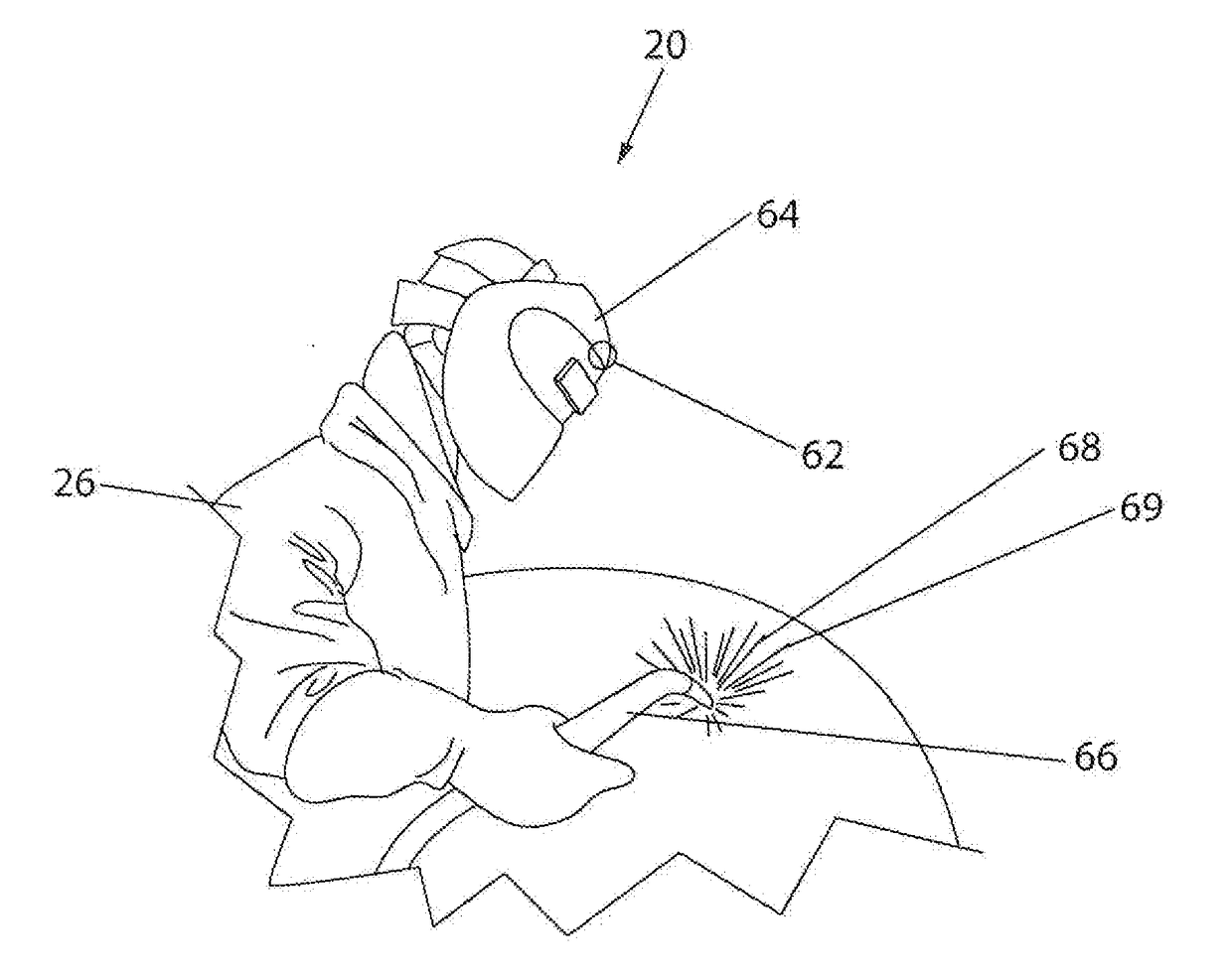
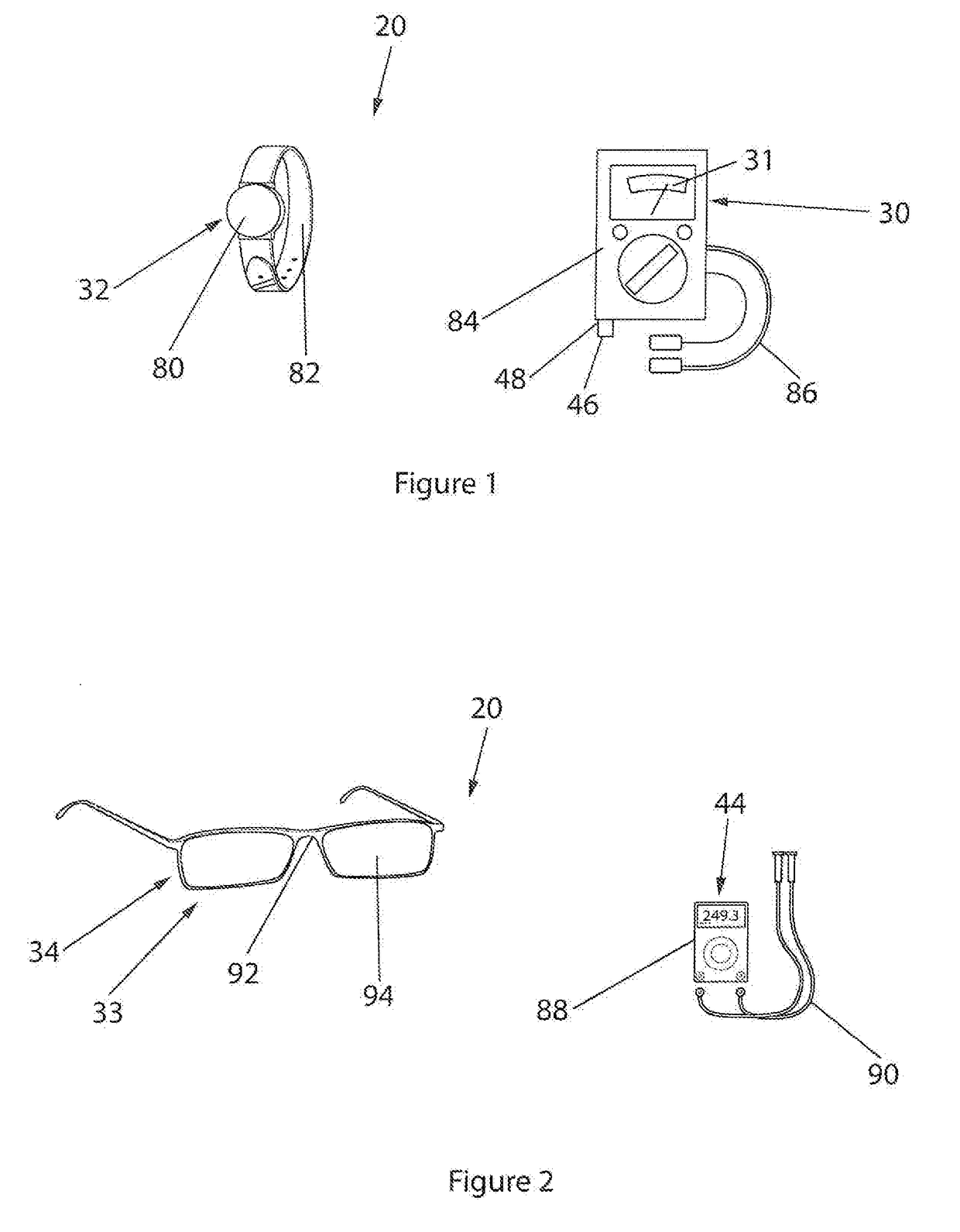
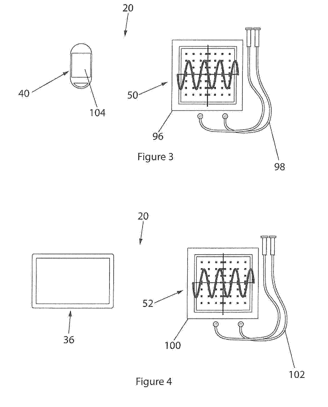
[0032]As discussed above, the prior art has failed to offer various test equipment that can be used with a wearable device capable of displaying measurements or readings relating to the test equipment. The proposed invention connects a wearable display device to electronic test equipment wirelessly. For instance, readings from a handheld multi-meter could be displayed on a smart watch. Similarly, a bench top multi-meter could be connected to a head mounted display, such as a pair of smart glasses like Google Glass. Further still, a machining tool, such as a vertical mill or lathe, could be connected to a wearable display to allow a user to focus on a piece being machined, while seeing changes in tool position. Other test equipment could be used with wearable dev...


PUM


Abstract

Systems and methods for a test equipment interface are described. The test equipment interface includes a test equipment device and a wearable device that are in wireless communication with one another. The wearable device displays information collected or measured by the test equipment device. As a result, a user can operate the test equipment device while receiving measurements. The wearable device may include a smart watch, a pair of smart glasses, a cellular telephone, or a tablet. The test equipment device may include electrical test equipment, machining tool, welding machinery, or a medical measuring device. The test equipment interface may operate using voice recognition technology. Additionally, the test equipment interface may have text-to-speech functionality, such that measurements can be audibly communicated. The test equipment interface may also include an application that displays, stores, analyzes, and catalogs any information taken by the test equipment device for later review.

Description

CROSS-REFERENCE(S) TO RELATED APPLICATION(S)[0001]This application claims the benefit of priority on U.S. Provisional Patent Application Ser. No. 62 / 299,603, filed on Feb. 25, 2016 and entitled Test Equipment Interface, the entirety of which is hereby incorporated by reference.BACKGROUND OF THE INVENTION[0002]1. Field of the Invention[0003]The present invention relates in general to the field of test equipment. More particularly, the present invent relates to a wearable device mounted to a user that is capable of displaying information taken from test equipment. Specifically, a preferred embodiment of the present invention relates to a wearable device that displays measurements taken from a multi-meter, an oscilloscope, a spectrum analyzer, a machining tool, a welding machine, a medical device and the like.[0004]2. Discussion of the Related Art[0005]Historically, a variety of different test equipment has been made available to measure various properties. For instance, electronic tes...

Claims


Application Information

Patent Timeline
Patent Type & Authority Applications(United States)
IPC IPC(8): G08C17/02A61B5/021H04N7/18G06F3/16G06F19/00H04N5/33G16Z99/00
CPCG08C17/02G06F19/3406H04N5/33G08C2200/00G06F3/167A61B5/021H04N7/185A61B5/0002A61B5/681H04Q2209/43H04Q2209/86H04Q9/00H04Q2209/823G16H40/63G16Z99/00
Inventor SHROAT, RYAN MICHAEL JOHNSON
Owner PLATO ELECTRONICS LLC
Why Eureka
Try Eureka