
Fastener

a technology of fasteners and screws, applied in the direction of threaded fasteners, screws, etc., can solve the problems of poor fastening effect of screw b>1/b>, poor flexibility and torque values of screw b>1/b>, and screw b>1/b> having some problems, etc., to achieve the effect of firm fastening

Inactive Publication Date: 2017-09-07
ESSENCE METHOD REFINE
View PDF7 Cites 8 Cited by
  • Summary
  • Abstract
  • Description
  • Claims
  • Application Information

AI Technical Summary

Benefits of technology

The invention is a fastener that prevents the fastener from snapping and reduces vibration after it is screwed into an object. The fastener has a shank with a root, head, and drilling portion. It has multiple main threads with inclined cutting faces that improve drilling efficiency. A main lobe is present on each main thread and contributes to torque and flexibility, increasing resistance to snapping and reducing vibration. Overall, the fastener provides a secure and efficient fastening.

Problems solved by technology

The screw 1 has some problems in the use.
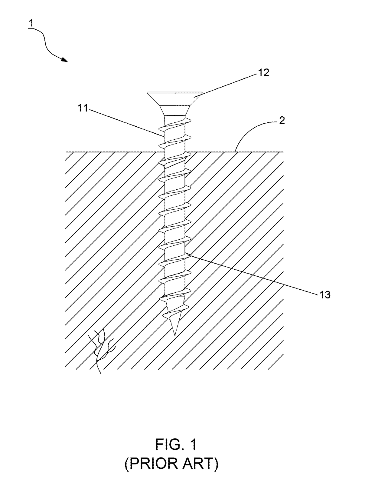
The screw 1 has poor flexibility and poor torque values because of the uneven portion formed on the shank 11 and this even portion snaps easily under a large drilling stress, with the result that the fastening effect of the screw 1 is not good.
However, the high temperature of the thermal treatment for processing threads renders the thin threads 13 a higher superficial temperature and causes the threads 13 to split and break easily under a slight pressure of the drilling action.
Thus, the drilling action becomes slow, not fast.
This also slows the drilling action down.

Method used


Image

  • Fastener
  • Fastener
  • Fastener

Examples


fourth embodiment

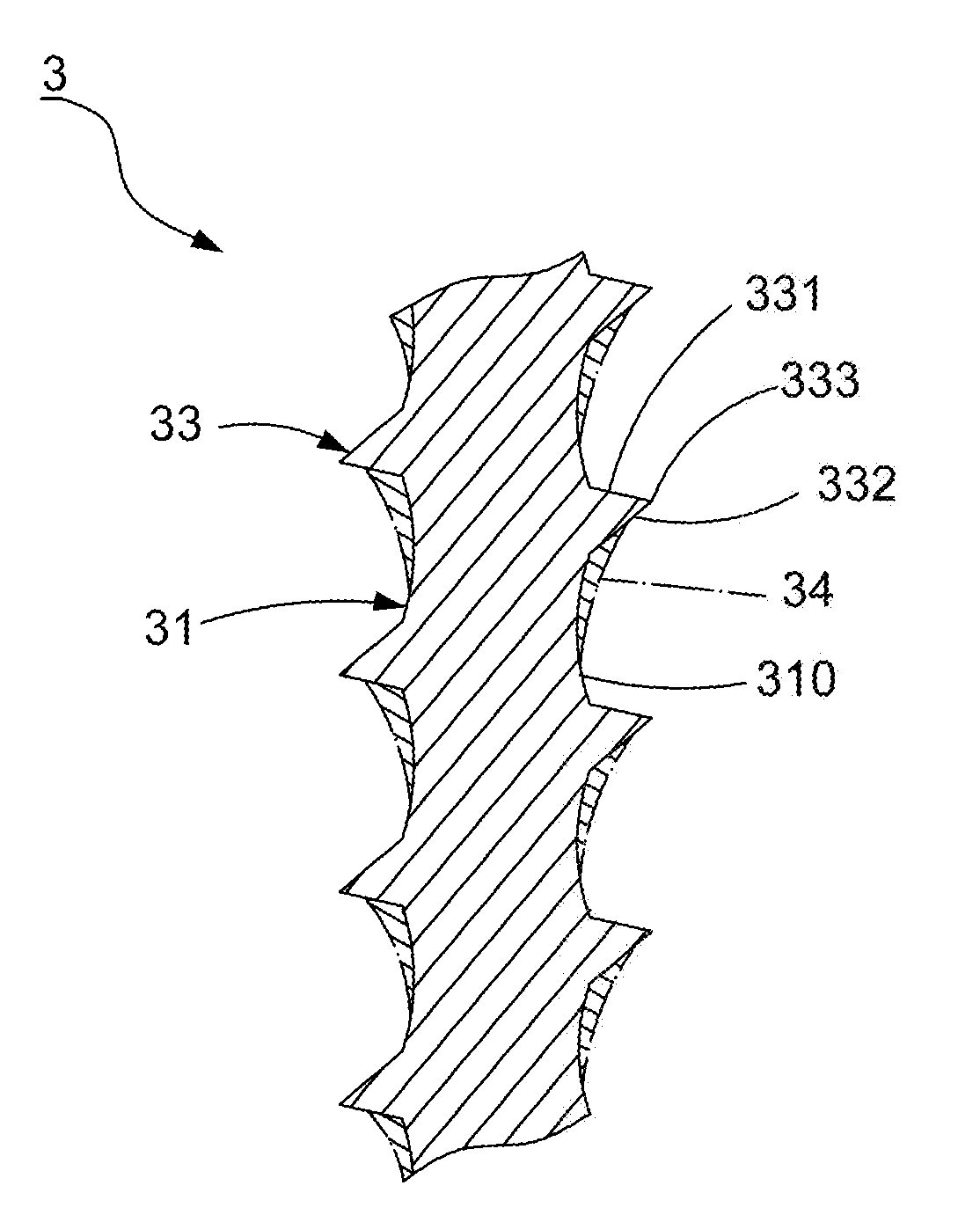
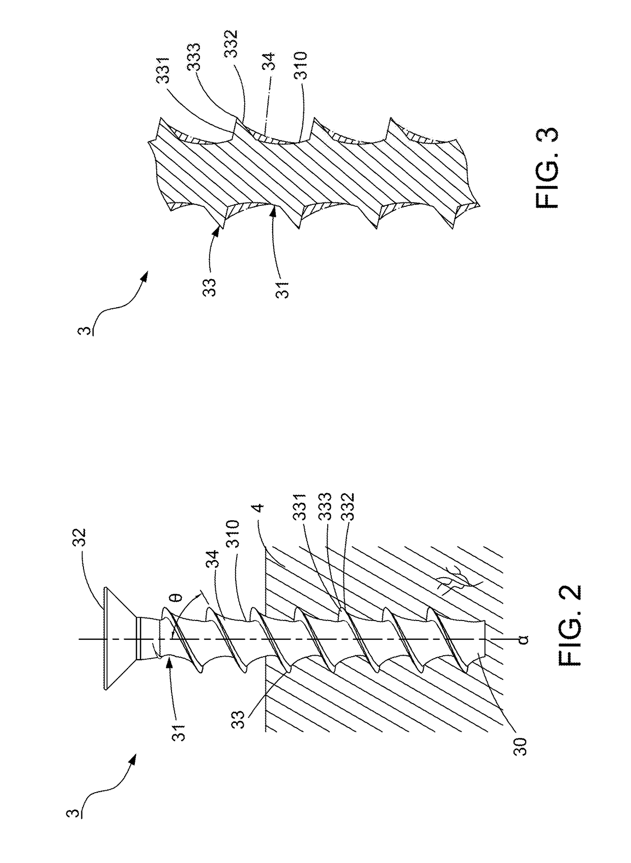
[0048]Referring to FIGS. 14-15, a sixth preferred embodiment of this invention has the same elements as those of the Particularly, this embodiment is to project at least one support lobe 37 from the shank 31. In other words, at least one support lobe 37 projects from the recessed root section 310 of the shank root to at least one auxiliary cutting face 351, 352 of the auxiliary thread 35. The support lobe 37 can be formed in a curved shape and flare outward to at least a midpoint of either one or both of the auxiliary cutting faces 351, 352 between the recessed root section 310 and the auxiliary edge 353. This support lobe 37 is also applied to the structure of FIG. 12, and the combination is shown in FIGS. 16-17 by having the support lobes 37 projecting from the recessed root section 310 to at least one or all auxiliary cutting faces 351, 352 of the two auxiliary threads 35. Therefore, the shank 31 with the main lobes 34 in cooperation with the support lobes 37 forms a multi-curve...

eighth embodiment

[0050]Referring to FIG. 21, a ninth preferred embodiment of this invention, having the same elements as those of the eighth embodiment, is characterized in that plural notches 333 are formed on each of the main threads 33. The notches 333 are also applied to different preferred embodiments presented supra. For example, FIGS. 22-24 show the notches 333 are incorporated into structures of FIG. 6, FIG. 14 and FIG. 16 respectively. By the main lobe 34 or the main lobe 34 in cooperation with the support lobe 37, good torsion resistance and tensile strength against the drilling stress can be attained to prevent the fastener 3 from snapping unintentionally. The notches 333 increase the cutting capability of the main threads 33 and facilitate the removal of the debris, thereby reducing the friction and drilling resistance and increasing the screwing efficiency and screwing engagement.

[0051]The advantages of this invention are as follows:[0052]1. Because the main thread 33 is inclined with r...


PUM

PropertyMeasurementUnit
angleaaaaaaaaaa
angleaaaaaaaaaa
inclined angleaaaaaaaaaa

Abstract

A fastener includes a shank defining a shank root, a head, a drilling portion and main threads. The main threads divide the shank root into recessed root sections. Each main thread with two cutting faces which converge at an edge is inclined to a shank axis by 60 to 82 degrees. At least one main lobe projects from the recessed root section and flares outward to at least a midpoint of at least one cutting face between the recessed root section and the edge of the main thread. The inclination allows the main threads to have a large rotating angle for increasing cutting and drilling efficiency. The extension of the main lobe supports the main thread to bear the drilling stress to prevent the shank and main threads from snapping and allow debris accommodation to provide a firm fastening effect.

Description

CROSS-REFERENCE TO RELATED APPLICATION[0001]This invention is a continuation-in-part of the U.S. patent application Ser. No. 14 / 540,246, filed on 13 Nov. 2014, currently pending, of which the subject matter is incorporated herein by reference in its entirety.BACKGROUND OF THE INVENTION[0002]1. Field of the Invention[0003]This invention relates to a fastener and relates particularly to a fastener with a good fastening effect and better mechanical characteristics, such as good performance for torsion resistance and tensile strength.[0004]2. Description of the Related Art[0005]Referring to FIG. 1, a conventional screw 1 includes a shank 11, a head 12 disposed on one end of the shank 1 and a plurality of threads 13 spirally disposed on the shank 11. To speed up the drilling action, the thickness of the thread 13 is reduced to sharpen the thread 13. In use, a rotary force is imparted to the head 12 to drill the threads 13 into an object 2 and screw the screw 1 into the object 2.[0006]The...

Claims


Application Information

Patent Timeline
Patent Type & Authority Applications(United States)
IPC IPC(8): F16B25/00
CPCF16B25/0047F16B25/0068F16B25/0015F16B25/0021F16B25/0078
Inventor CHEN, LING-FANG
Owner ESSENCE METHOD REFINE
Learn More