Reconfigurable casing antenna system

a casing antenna and antenna system technology, applied in the direction of antenna supports/mountings, particular array feeding systems, antennas, etc., can solve the problems of limited ability to provide adequate isolation between each radiator, and configuration may not be ideal or even practical

Inactive Publication Date: 2017-09-07
SMART ANTENNA TECH
View PDF3 Cites 18 Cited by
  • Summary
  • Abstract
  • Description
  • Claims
  • Application Information

AI Technical Summary

Benefits of technology

[0056]By providing a degree of antenna redundancy around the periphery, present embodiments may address the problem of a user holding the handset in different ways. For example, when the handset is held at the bottom, then the antennas at the top of the handset will work. When the handset is held at the top, then the antennas at the bottom of the handset will work. When the handset is held in a landscape position, the user's hands might cov...

Problems solved by technology

However, very few portable devices with MIMO capability are available in the marketplace.
The main reason for this is that, when gathering several radiators in a portable device, the small allocated space for the antenna limits the ability to provide adequate isolation between each radiator.
However, in certain applications...

Method used


Image

  • Reconfigurable casing antenna system
  • Reconfigurable casing antenna system
  • Reconfigurable casing antenna system

Examples


first embodiment

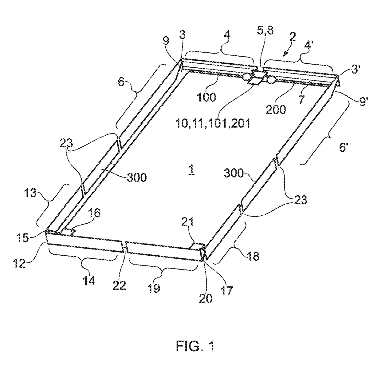
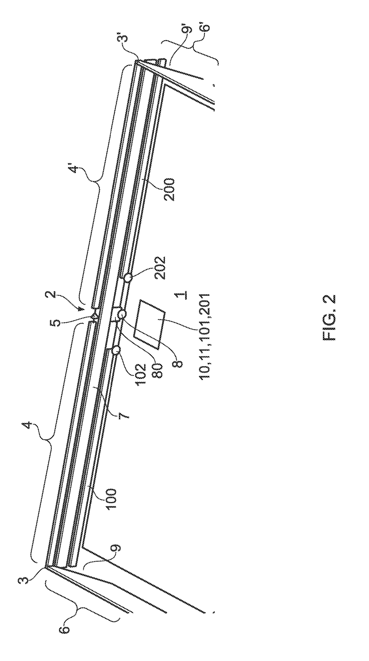
[0066]A first embodiment is shown in FIGS. 1 and 2. There is provided a substrate 1, which may be a PCB of a mobile telephone handset, the substrate 1 including a conductive groundplane over a majority of its area. The antenna device forms a generally rectangular frame around the substrate 1, and may be incorporated into a casing (not shown) of the mobile handset (not shown), for example as a bezel or the like. Alternatively, the antenna device may be mounted to an interior surface of the casing of the mobile handset, as required by design and aesthetic considerations.

[0067]The antenna device of this embodiment comprises six distinct antennas, each of which is provided with a matching circuit connected to a signal port, the matching circuits and signal ports being mounted on the substrate 1.

[0068]A first balanced antenna 2 is provided at the top edge of the substrate 1, and comprises first and second radiating arms 3, 3′. Each radiating arm 3, 3′ has a proximal portion 4, 4′ extendi...

second embodiment

[0077]FIG. 4 shows a second embodiment, with the various components labelled as in FIG. 1. In this embodiment, the first unbalanced antenna 7 is disposed in the same plane as the substrate 1, or in a parallel plane. The first unbalanced antenna 7 may be mounted directly on a groundplane-free region at the top edge of the substrate 1, or may be formed as a separate element above the top edge of the substrate 1 as shown in FIG. 3. The matching circuit and signal port 10 for the first balanced antenna 2 may be mounted on a floating groundplane provided on a central part of the first unbalanced antenna 7.

[0078]The embodiment of FIG. 4 also includes a second unbalanced antenna 24 at the left side of the substrate 1 and a third unbalanced antenna 25 at the right side of the substrate 1. The second and third unbalanced antennas 24, 25 are respectively located between the ends of the first radiating arms 13, 18 of the second and third balanced antennas 12, 17 and the ends of the distal port...

third embodiment

[0080]FIG. 6 shows a third embodiment, which is similar to that of FIG. 1, but includes the unbalanced antennas 24, 25 of the FIG. 4 embodiment as fourth and fifth unbalanced antennas in addition to the second and third unbalanced antennas 100, 200. The embodiment of FIG. 6 thus has three balanced antennas 2, 12, 17 and five unbalanced antennas 7, 100, 200, 24, 25 distributed around the periphery. An additional metal or non-metal spacer 300 may be provided on the bottom edge for cosmetic reasons and optionally to help reduce unwanted coupling between balanced antennas 12 and 17.

[0081]FIG. 7 is a system block showing how the antenna device of the FIG. 6 embodiment, comprising eight separate antennas, can be provided with suitable matching circuitry to drive 13 signal ports. Using high pass and low pass filters 400, 401 and matching circuits 402, 402′, it is possible for a single antenna element to handle two independently tuneable RF signals, as described in more detail in the presen...


PUM


Abstract

There is disclosed a reconfigurable antenna device comprising a plurality of antennas disposed about a periphery of a substantially rectangular shape having top, bottom, left and right sides. The antenna device includes a first balanced antenna having first and second radiating arms each having a proximal portion and a distal portion, proximal portions extending along the top side in respectively opposed directions from a substantially central feed point, and the distal portions extending part way down the left and right sides. The antenna device further includes a first unbalanced antenna located generally between the distal portions and adjacent to the proximal portions of the first and second radiating arms. In addition, the antenna device includes a second balanced antenna having a first radiating arm extending up the left side from a feed peed point in a bottom left corner of the periphery and a second radiating arm extending along the bottom side from the feed point in the bottom left corner of the periphery, and a third balanced antenna having a first radiating arm extending up the right side from a feed point in a bottom right corner of the periphery and a second radiating arm extending along the bottom side from the feed point in the bottom right corner of the periphery.

Description

[0001]This invention relates to a reconfigurable antenna. Particularly, but not exclusively, the invention relates to a reconfigurable multiple-input multiple-output (MIMO) casing antenna for use in a portable electronic device such as a mobile phone handset.BACKGROUND[0002]Multiple-input multiple-output (MIMO) wireless systems exploiting multiple antennas as both transmitters and receivers have attracted increasing interest due to their potential for increased capacity in rich multipath environments. Such systems can be used to enable enhanced communication performance (i.e. improved signal quality and reliability) by use of multi-path propagation without additional spectrum requirements. This has been a well-known and well-used solution to achieve high data rate communications in relation to 2G and 3G communication standards. For indoor wireless applications such as router devices, external dipole and monopole antennas are widely used. In this instance, high-gain, omni-directional...

Claims


Application Information

Patent Timeline
IPC IPC(8): H01Q1/24H01Q9/26H01Q5/335H01Q21/00H01Q21/28H01Q1/48
CPCH01Q1/243H01Q21/28H01Q1/48H01Q9/26H01Q21/005H01Q21/0068H01Q5/335H01Q1/2266H01Q9/16H01Q9/20H01Q9/42H01Q9/44H01Q5/50H01Q1/2258
Inventor HU, SAMPSONWANG, ZHENGPENGGAO, XIANG
Owner SMART ANTENNA TECH
Why Eureka
Try Eureka