Distributed feedback laser

a laser and feedback technology, applied in the direction of laser optical resonator construction, laser details, active medium shape and construction, etc., can solve the problems of affecting performance, wasting half of output power, sharp increase in threshold gain, etc., to improve the direct-modulation bandwidth of the laser, improve the feedback of the laser, and reduce the threshold gain

Inactive Publication Date: 2017-09-07
HUAZHONG UNIV OF SCI & TECH +1
View PDF3 Cites 0 Cited by
  • Summary
  • Abstract
  • Description
  • Claims
  • Application Information

AI Technical Summary

Benefits of technology

[0018]The Bragg grating is introduced to the reflecting region to improve the feedback of the laser, which is equivalent to coat a high-reflecting film on an end facet of the active region, thus reducing the threshold gain, making the laser work at a short cavity length (200 μm or less), and improving the direct-modulation bandwidth of the laser. In addition, the slop efficiency of the output from the laser can be improved, and the reflective phase produced by the second grating of the reflecting region is controllable, thus not leading to the reduction of the side mode suppression ratio. In the meanwhile, the active region and the reflecting region adopt the same waveguide core layers, and the formation of the reflecting region does not require complicate butt-joint regrowth process any more, thus possessing reduced fabrication difficulties.

Problems solved by technology

However, only the output from one end is usually coupled to optical fibers, which means that half of the output power is wasted.
However, when the cavity length is reduced to 200 μm or below, the threshold gain increases sharply, which adversely affects the performance.

Method used


Image

  • Distributed feedback laser
  • Distributed feedback laser
  • Distributed feedback laser

Examples


Embodiment Construction

[0024]For further illustrating the invention, experiments detailing a distributed feedback laser are described below. It should be noted that the following examples are intended to describe and not to limit the invention.

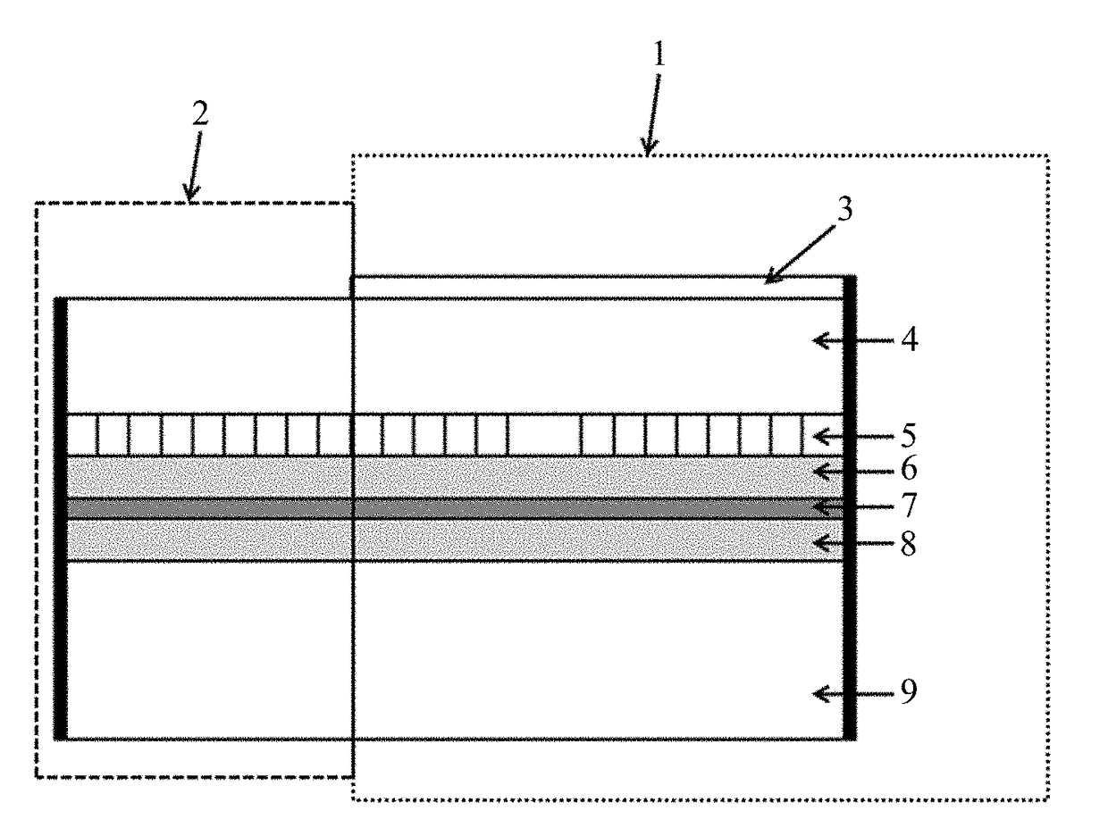
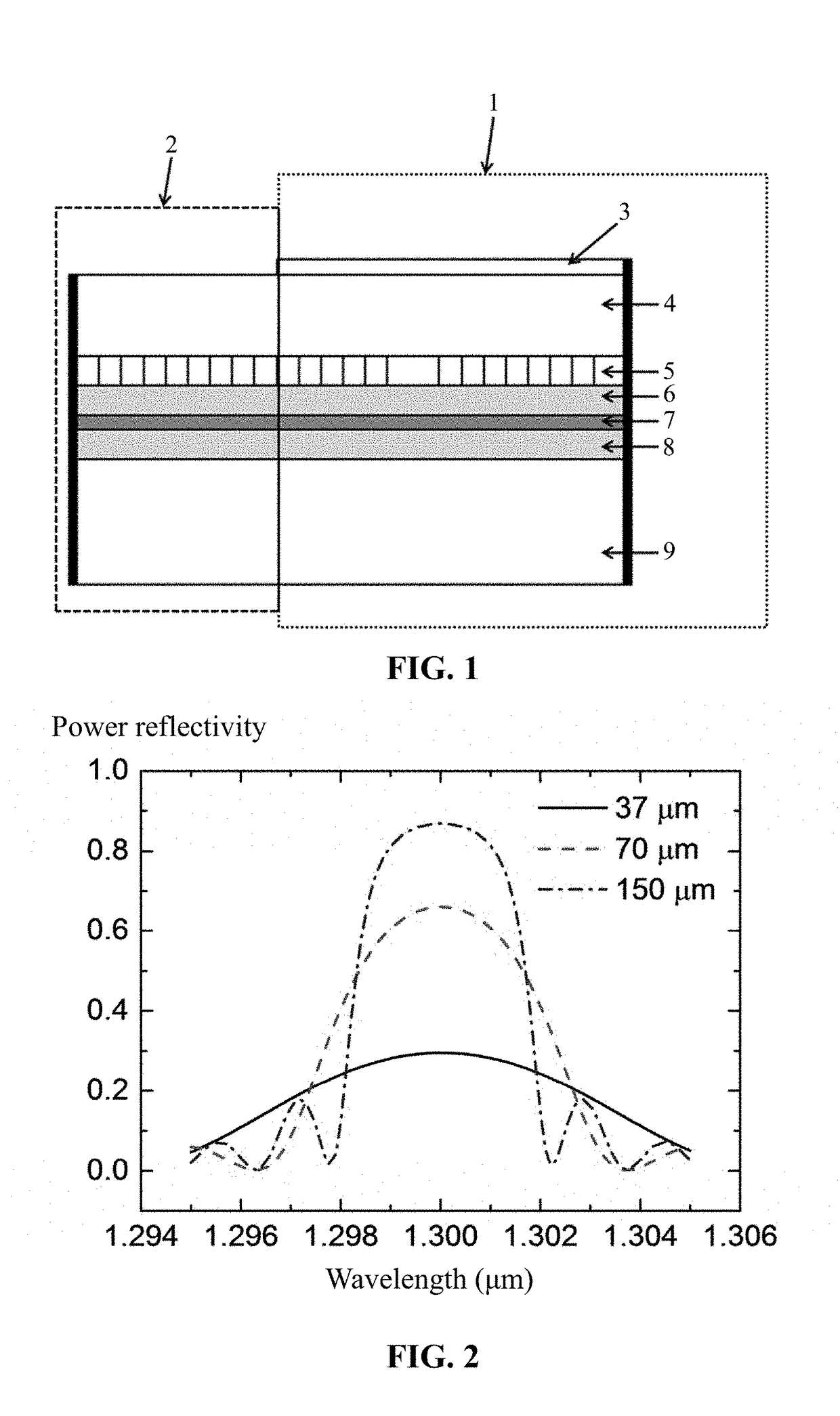
[0025]A distributed feedback laser having a short cavity length is illustrated in FIG. 1. The distributed feedback laser comprises: an active region 1, also called an optical gain region, and a reflecting region 2. The active region 1 comprises, from the top down: an electric contact layer 3, a waveguide upper cladding layer 4, a grating layer 5, an upper optical confinement layer 6, a Multi-quantum well layer 7, a lower optical confinement layer 8, and a waveguide lower cladding layer 9. The reflecting region 2, from the top down, comprises: a waveguide upper cladding layer 4, a grating layer 5, an upper optical confinement layer 6, a Multi-quantum well layer 7, a lower optical confinement layer 8, and a waveguide lower cladding layer 9. The grating layer of the ac...


PUM


Abstract

A distributed feedback laser, including: an output end including an active region including a grating including a λ/4 phase-shift region; and a non-output end including a reflecting region including a grating with uniform period. The length of the active region is smaller than or equal to 200 μm. The end facet of the output end of the laser is coated with an anti-reflection film.

Description

CROSS-REFERENCE TO RELATED APPLICATIONS[0001]This application is a continuation-in-part of International Patent Application No. PCT / CN2016 / 086143 with an international filing date of Jun. 17, 2016, designating the United States, now pending, and further claims foreign priority benefits to Chinese Patent Application No. 201510354846.X filed Jun. 24, 2015. The contents of all of the aforementioned applications, including any intervening amendments thereto, are incorporated herein by reference. Inquiries from the public to applicants or assignees concerning this document or the related applications should be directed to: Matthias Scholl P. C., Attn.: Dr. Matthias Scholl Esq., 245 First Street, 18th Floor, Cambridge, Mass. 02142.BACKGROUND OF THE INVENTION[0002]Field of the Invention[0003]The invention relates to a distributed feedback laser.[0004]Description of the Related Art[0005]Conventional λ / 4 phase-shift distributed feedback lasers include anti-reflection films at two ends, and t...

Claims


Application Information

Patent Timeline
Patent Type & Authority Applications(United States)
IPC IPC(8): H01S3/067H01S3/06H01S3/063
CPCH01S3/0675H01S3/0635H01S3/1305H01S3/1055H01S3/10023H01S3/0623H01S5/0035H01S5/0287H01S5/1085H01S5/125H01S5/16H01S5/124
Inventor GUO, WEIHUAZHAO, GONGYUANLU, QIAOYIN
Owner HUAZHONG UNIV OF SCI & TECH
Why Eureka
Try Eureka