Switchgear enclosure with interconnected exhaust system

an exhaust system and switchgear technology, applied in the field of switchgear, can solve the problems of significant energy release, damage to the conductors and adjacent equipment of the switchgear,

Active Publication Date: 2017-09-07
ABB (SCHWEIZ) AG
View PDF9 Cites 11 Cited by
  • Summary
  • Abstract
  • Description
  • Claims
  • Application Information

AI Technical Summary

Problems solved by technology

If an arc occurs, such as if a voltage between the conductors within the switchgear exceeds the insulative properties of the insulation between the conductors, or if the conductors are positioned too closely together, an arc flash can release significant energy in the form of heat, intense light, pressure waves, and / or sound waves, sufficient to damage the conductors and adjacent equipment of the switchgear.

Method used


Image

  • Switchgear enclosure with interconnected exhaust system
  • Switchgear enclosure with interconnected exhaust system
  • Switchgear enclosure with interconnected exhaust system

Examples


Embodiment Construction

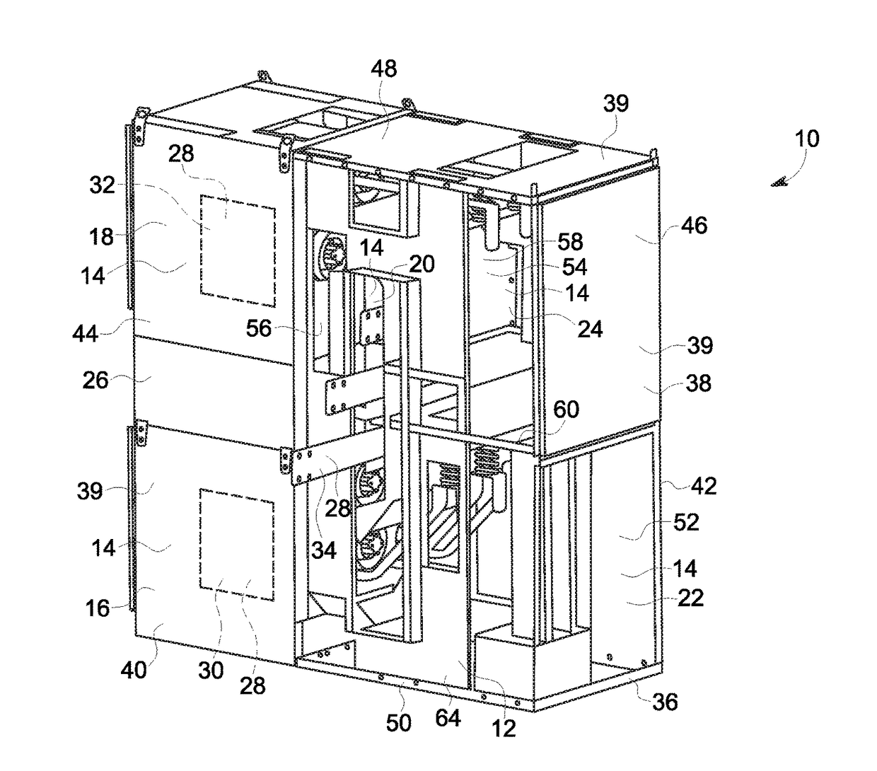
[0017]Various embodiments disclosed herein provide arc resistant switchgears with an interconnected exhaust system. More specifically, the switchgears described herein include a plurality of switchgear panels with a vent structure that directs arc gases from within various compartments of the switchgears to a gas duct to be exhausted from the switchgear. The switch gear includes one or more ducts that extend through the vent structures of the switchgear panels to distribute the gases through the switchgear. By distributing the gases, the switchgear may facilitate reducing peak pressure within the switchgear and reducing time to reach the peak pressure.

[0018]FIG. 1 illustrates one embodiment of an arc resistant switchgear 10 (also referred to as a “switchgear panel”) with an exhaust system 12 to exhaust from multiple compartments 14 to atmosphere. In the exemplary embodiment, compartments 14 include a first (lower) circuit breaker compartment 16, a second (upper) circuit breaker comp...


PUM


Abstract

A switchgear enclosure is provided. The switchgear enclosure includes a plurality of switchgear panels and a plurality of ducts extending through the switchgear panels. Each switchgear panel includes an exterior housing, a busbar compartment defined within the exterior housing, and an exhaust system. The busbar compartment surrounds a busbar extending through the switchgear panel. The exhaust system includes a vent path structure configured within the exterior housing to at least partially surround the busbar compartment, a first channel defined between the vent path structure and the exterior housing, and a first vent opening formed on the vent path structure. The first vent opening directs arc gases within said busbar compartment to the first channel. The ducts are in fluid communication with the first channels of the switchgear panels to distribute arc gases between the first channels.

Description

BACKGROUND[0001]Embodiments of the present invention relate generally to switchgear, and more particularly, relates to a switchgear enclosure having an interconnected exhaust system.[0002]Switchgear, such as medium voltage (“MV”) switchgear, includes various components secured within an enclosed structure. The switchgear enclosure is divided into compartments, such as one or more circuit breaker compartments each housing a circuit breaker, a busbar compartment housing a busbar system, and one or more cable connection compartments. The circuit breakers in the circuit breaker compartments can be electrically connected to the busbar system in the busbar compartment via spouts.[0003]If an arc occurs, such as if a voltage between the conductors within the switchgear exceeds the insulative properties of the insulation between the conductors, or if the conductors are positioned too closely together, an arc flash can release significant energy in the form of heat, intense light, pressure wa...

Claims


Application Information

Patent Timeline
Patent Type & Authority Applications(United States)
IPC IPC(8): H02B1/56H02B13/00
CPCH02B13/005H02B1/565H02B1/26H02B13/025H02B5/06
Inventor RAJAURIA, SAMIRMEINERS, STEVEN EDWARDWU, HAOJAKKIREDDY, AYYAPPA REDDYKURRA, GURU MOORTHY
Owner ABB (SCHWEIZ) AG
Why Eureka
Try Eureka