
Device and method for orchestrating display surfaces, projection devices, and 2d and 3D spatial interaction devices for creating interactive environments

a technology of projection device and display surface, applied in the direction of color television, image data processing, instruments, etc., can solve the problems of low user experience, low cost of environment, and high implementation cost, and achieve the effect of reducing the cost of prototyping and evaluation of new functionalities in these environments, and reducing the cost of implementation

Inactive Publication Date: 2017-09-07
INGENUITY I O
View PDF3 Cites 6 Cited by
  • Summary
  • Abstract
  • Description
  • Claims
  • Application Information

AI Technical Summary

Benefits of technology

The invention is about a device and method for creating a multimodal interactive environment where multiple display surfaces, video projection devices, and spatial interaction devices can be unified in a three-dimensional coordinate system. The device can adapt the geometry of projected images to the surfaces and can manage tactile interactions on the projection surfaces. The method can integrate 2D and 3D spatial interaction devices and can project images in real-time as a function of the user's actions. The invention allows for the creation of a simulated or partially simulated environment that can be tailored to the user's needs and can provide the user with a display equivalent to a real environment.

Problems solved by technology

The proliferation of devices necessary for the production of these interactive environments in which the user will have access to the proposed functionalities means that these environments are generally very expensive and complex to put in place, thereby rendering the prototyping and the evaluation of new functionalities in these environments less obvious.
On the one hand, the hardware necessary to create a really immersive virtual reality experience, that is to say in which the user is not a mere spectator but can interact with the virtual environment as he would with the real environment, is fairly prohibitive, thereby restricting its use to research and to certain business sectors where security constraints are more significant than budgetary constraints.
Moreover, even with a very immersive virtual reality experience of quality, the results obtained will not necessarily be representative of usage in the real world.
The virtual world does not necessarily reproduce the real environment in all its details (sound and lighting conditions, vibrations, etc.) and it is not suitable for collaboration because virtual avatars do not make it possible to faithfully transcribe the mutual relative positions of the users and non-verbal communication (gestures, attitudes, facial mimics, etc.).
A major drawback of this approach is that the user must be kitted out with a pair of augmented reality glasses and this may be fatiguing for lengthy evaluations and requires equipment suitable for the sight (corrective glasses, contact lenses, etc.) of all the users participating in the evaluation, and this may be fairly expensive.
Another major drawback is that each user has his own subjective view of the augmented real world, this not facilitating the creation of a shared context in situations of co-located collaboration: even if the virtual world overlaid on reality is shared, the various users do not see exactly the same thing, more particularly the virtual world presented to user may mask the hands of a second user thus preventing the first user from being fully aware of his collaborators actions.
A drawback of this approach is that computer vision is very sensitive to occlusion: one user may mask another users actions by placing his arm or his hand between him and the camera, thus rendering him invisible to the camera.
Moreover, computer vision may be disturbed by the use of display devices, such as screens, within the field of the camera: light and heat emitted by these display devices may be perceived by the camera and lead to false positives.
Computer vision has difficulty managing dynamic changes of the environment because this technique relies on comparing a current image with a starting condition.

Method used


Image

  • Device and method for orchestrating display surfaces, projection devices, and 2d and 3D spatial interaction devices for creating interactive environments
  • Device and method for orchestrating display surfaces, projection devices, and 2d and 3D spatial interaction devices for creating interactive environments

Examples


Embodiment Construction

[0053]In the present mode of implementation, given here by way of nonlimiting illustration, a device according to the invention is used within the framework of the generation of a cockpit simulator. It will be referred to subsequently by the term simulation management device.

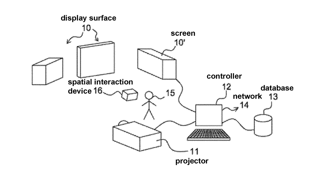
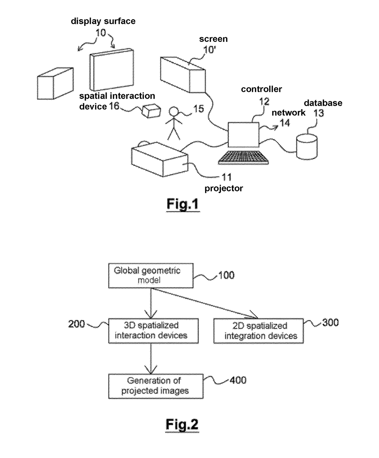
[0054]As seen in FIG. 1, the simulation management device uses for its implementation a plurality of display surfaces 10 not necessarily plane, nor necessarily parallel, connected or coplanar. The invention can naturally be implemented on a single surface, but finds its full use only for the generation of images toward several surfaces.

[0055]The display surfaces 10 considered here are in particular of passive type. That is to say that they may typically be surfaces of cardboard boxes, of boards, etc. In one embodiment given by way of simple illustrative example, the display surfaces 10 consist of a set of cardboard boxes of various sizes, disposed substantially facing a user 15 of said simulation management devi...


PUM


Abstract

A device to manage the projection of images onto a plurality of media, and to geometrically designate and model a plurality of selected areas on display surfaces. The display areas form a visual environment of a user. The designations and models result in an environmental geometric model. A controller interprets information provided by at least one spatial interaction device of the user in the environmental geometric model. The controller generates images to be projected onto the various display areas by at least one image projector in accordance with the actions of the user as detected by the spatial interaction devices.

Description

[0001]The present invention pertains to the domain of information presentation devices and interaction devices. It pertains more particularly to devices for projecting and displaying digital images on multiple physical surfaces taking into account the interactions of one or more users with this mainly visual environment but that can be extended to the sound domain and to any spatialized information device.PREAMBLE AND PRIOR ART[0002]Computing is a universe that is perpetually evolving from various standpoints: hardware, software, architecture and uses. Computing began in the 1950s on the model of the fixed central unit (mainframe) used by several people, before evolving toward the model of personal computer in the 1980s, of computers interconnected via the Internet in the 1990s and ultimately evolving toward ubiquitous or pervasive computing where the user is surrounded by a set of computing devices with which he can interact or that he can use to monitor his environment.[0003]These...

Claims


Application Information

Patent Timeline
IPC IPC(8): H04N9/31G06T19/00G09G3/00G06F3/14G06F3/01
CPCH04N9/3185G06F3/1423G06F3/017G09G2354/00G09G3/001G06T19/006G06F3/011G09B9/302G09B9/32H04N9/3194
Inventor VALES, STEPHANEPEYRUQUEOU, VINCENTLEMORT, ALEXANDRE
Owner INGENUITY I O
Learn More