Long-Term Therapeutic Pressure Applicator and Real-Time Monitoring System

a technology of pressure applicator and monitoring system, which is applied in the field of long-term therapeutic pressure applicator and real-time monitoring system, can solve the problems of not displaying the actual, applied force or pressure to increase or decrease, and the patient has no accurate way to tell how much pressure has deviated

Active Publication Date: 2017-09-14
RESPIRATORY TECH CORP
View PDF19 Cites 12 Cited by
  • Summary
  • Abstract
  • Description
  • Claims
  • Application Information

AI Technical Summary

Problems solved by technology

A problem with conventional medical devices that apply force or pressure to a patient is that they do not display the actual force or pressure being applied.
For example, the device can slide or shift up or down on the patient, the patient can lose or gain weight, experience swelling or become dehydrated, which can cause the applied force or pressure to increase or decrease.
The patient has no accurate way to tell how much the pressure has deviated from that set desired amount.
Without realizing it, the patient can allow the device to gradually increase or decrease to an improper or even potentially harmful setting.
In other situations, the patient will incorrectly believe the force or pressure has changed and is now too loose or tight, when the force or pressure has not changed.
The patient will then improperly adjust the device to increase or decrease the force or pressure to an improper or harmful setting.
Another problem with conventional medical devices that apply force or pressure to a patient is that they do not provide any objective evidence to the physician regarding the use of the device by the patient.
Should the patient forget these details or fail to a

Method used


Image

  • Long-Term Therapeutic Pressure Applicator and Real-Time Monitoring System
  • Long-Term Therapeutic Pressure Applicator and Real-Time Monitoring System
  • Long-Term Therapeutic Pressure Applicator and Real-Time Monitoring System

Examples


first embodiment

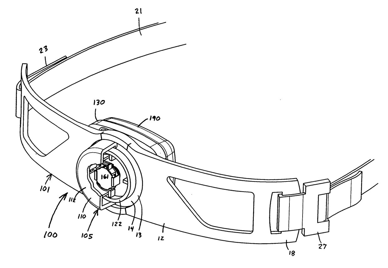
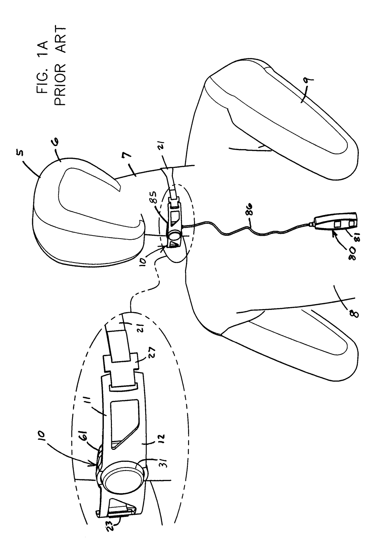
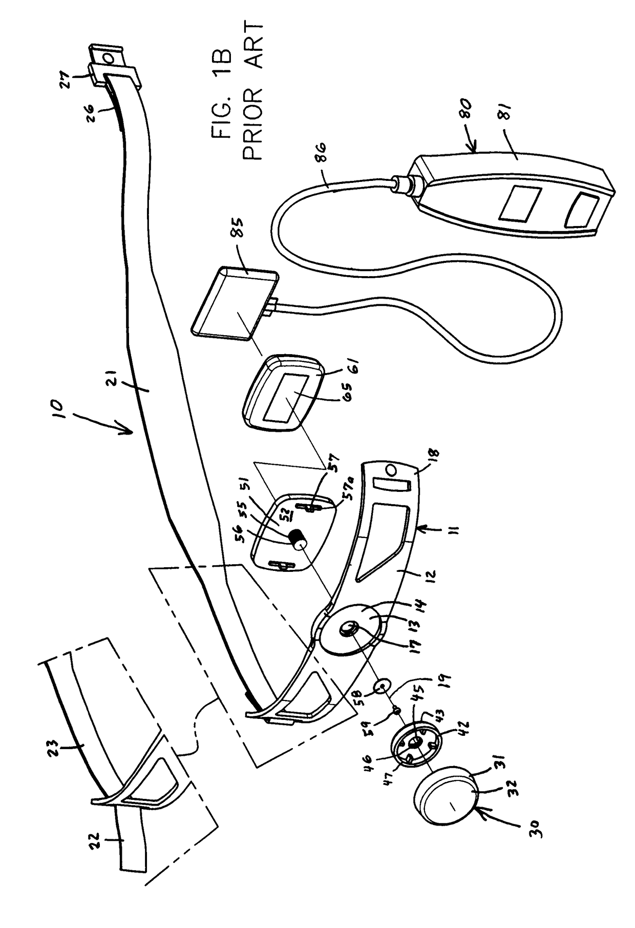
[0056]The present invention pertains to a long-term therapeutic pressure applicator and monitoring device generally indicated by reference numbers 100 and a real-time pressure monitoring system generally represented by reference number 200 as shown in FIGS. 2-11. The therapeutic pressure applicator and monitoring device 100 has a securing member or mechanism 101 to secure a pressure adjusting mechanism 105 to the patient 5. Depending on the body part involved, the securement member or mechanism 101 can take a variety of forms. In a first embodiment, the therapeutic pressure applicator and monitoring device 100 is secured to the neck 7 to reduce esophageal reflux as in FIGS. 2A-J. The securing mechanism 101 is the conventional Reza neck band 11 used by the treating physician to apply an approximate pressure to the patient that is close to the desired pressure. As noted above, the band 11 has the semi-flexible strap or securement bracket 12 with its central recess 13, front and rear s...

embodiment 300

Automated Applicator Embodiment 300

[0083]An automated embodiment of the therapeutic pressure applicator and monitoring device 300 is shown in FIGS. 3A and 3B. The automated device 300 automatically adjusts the pressure applied to the neck 5 of the patient 5 so that the applied pressure is at a specific predetermined pressure or within a specific predetermined pressure range. The applicator 300 has a securing mechanism 101 in the form of the conventional neck band 11, and many of the components of the pressure adjusting mechanism 305 of the applicator 300 are interchangeable with the pressure adjusting mechanism 105 of the manually applicator 100. The pressure adjusting mechanism 305 of the automated applicator 300 has the same pressure sensor sensing component 130, sensor 140, computer module 150, power supply 160, pressure focusing plate 180 and cushion 190 as the manual applicator 100. The pressure dial 310 and programming of the CPU 151 of the automated applicator 300 are modifie...

embodiment 400

Universal Bracket Embodiment 400

[0086]An embodiment of the therapeutic applicator 400 with a more universal securement mechanism is shown in FIGS. 4A and 4B. The applicator 400 has the same pressure adjusting mechanism 305 as in the automated applicator 300, but the securing mechanism 401 is in the form of a universal securing bracket 402. The bracket 402 has a central recess 403, front and rear surfaces 404 and 405, a central opening 407 and opposed lateral ends 408. The rear surface 405 of the strap bracket 402 has two spaced slots 415a. The common center of the central recess 403 and opening 407 forms a centerline 409 for the applicator 400. A strap (not shown) or some other form of fastener is secured to each of those lateral ends 408 to secure the device 400 to the body of a patient 5.


PUM


Abstract

This invention pertains to a therapeutic pressure applicator with a sensor and transceiver worn by a patient during daily activity to apply pressure to a specific body part during long term treatment, and used in a system with a device such as a cell phone to receive and display real-time pressure data to alert the patient and physician when the pressure is outside a desired range. The applicator includes a securement member and a pressure adjusting device with a pressure adjusting dial, pressure sensing component, pressure focusing plate and cushion. Rotating the dial retracts or extends the sensing component, focusing plate and cushion. The applicator has a computer module with a CPU, memory, transceiver, power source and a force sensor. The focusing plate aligns a pressure button into pressed engagement with the sensor to transmit real-time focused pressure data to the CPU, which converts the focused data into real-time cushion pressure data. The transceiver periodically communicates the long-term, real-time cushion pressure data to the cell phone that displays and stores the data.

Description

TECHNICAL FIELD OF THE INVENTION[0001]This invention relates to a therapeutic pressure applicator worn by a patient during normal daily activity to apply pressure to a specific body part and obtain real-time pressure data during long-term medical treatment, and used in a system including a device such as a cell phone to receive and display the pressure data to alert the patient and treating physician when the pressure is outside a desired range.BACKGROUND OF THE INVENTION[0002]Medical devices to apply compression or tension to the head, neck, torso, arm or other body part of a patient are well known. Conventional blood pressure monitors are secured to the arm, and inflate and deflate to determine blood pressure. Examples of these monitors are disclosed in U.S. Pat. No. 4,458,690 to O'Connor, U.S. Pat. No. 5,054,494 to Lazzara, U.S. Pat. No. 5,280,790 to Brooks, U.S. Pat. No. 7,052,465 to Lunak and U.S. Pat. No. 9,289,136 to Addison. Back braces are secured to the torso to apply pres...

Claims


Application Information

Patent Timeline
IPC IPC(8): A61H1/00A61B5/00
CPCA61H1/008A61B5/4848A61H2205/04A61H2201/5043A61H2201/5061A61H2201/0184A61H2205/025A61B5/6843A61C7/14A61H7/001A61H2201/0192A61H2201/1207A61H2201/165A61H2201/1695A61H2201/5097A61C7/065A61C19/04A61F5/01A61F5/32A61F2005/0172A61F2005/0188A61F2005/0155
Inventor ARMBRUST, DANIEL PAULGRABON, ROBERT JAMES
Owner RESPIRATORY TECH CORP
Why Eureka
Try Eureka