
Fuel cell

Inactive Publication Date: 2005-11-17
ATLANTIC PACIFIC FUEL CELL CORP
View PDF3 Cites 1 Cited by
  • Summary
  • Abstract
  • Description
  • Claims
  • Application Information

AI Technical Summary

Benefits of technology

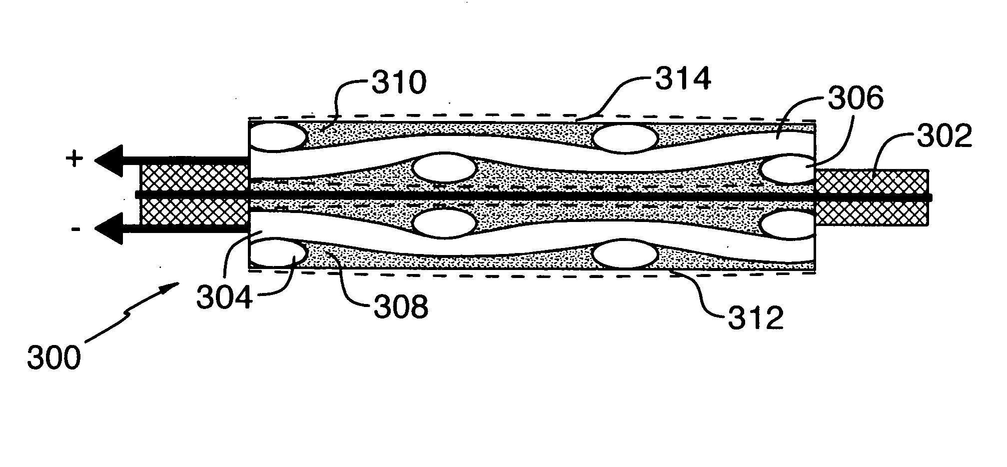
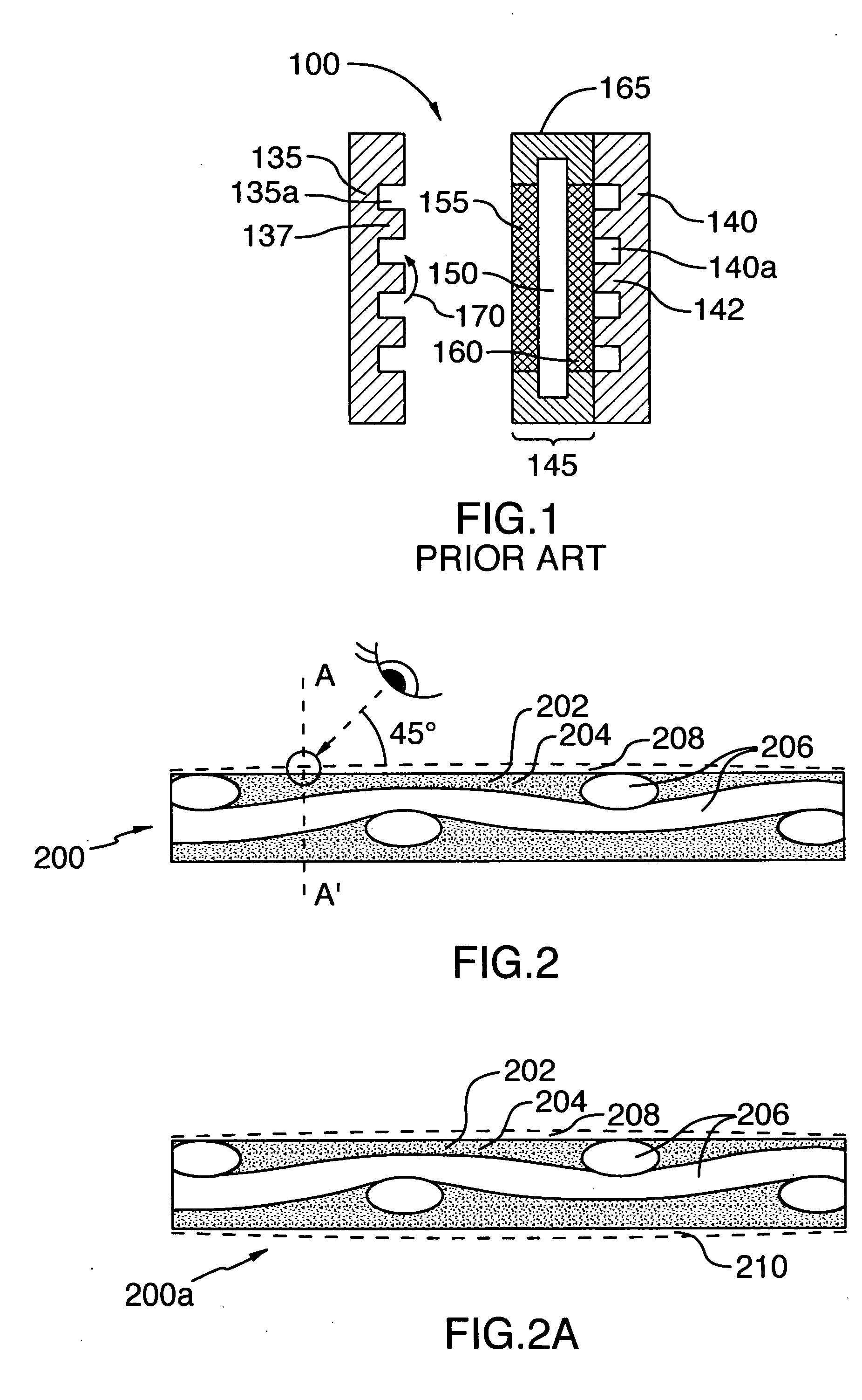
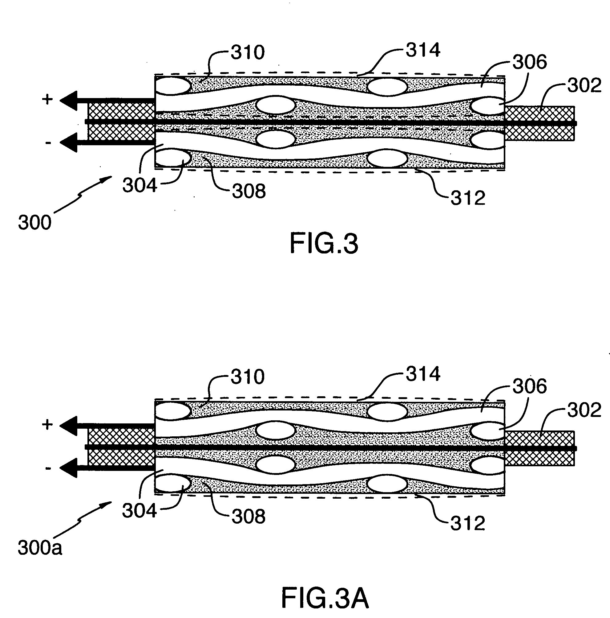
[0012] It is a further object to provide a fuel cell having a polymer with a relatively high surface area that can stabilize current and voltage behavior by absorbing the reactant hydrogen or oxygen gases into the porous polymer structure.
[0014] It is a further object to provide a fuel cell that has good electrochemical and mechanical performance and a stabilized current voltage output under varying load conditions.
[0033] Control of the catalyst density or size of the metallic catalyst clusters is achieved by increasing or decreasing the precious metal chloride concentration and by increasing or decreasing the contract time of the gas diffusion electrode with the chloride solution. The chloride solutions are allowed to contact the surface of the gas diffusion electrode using the commonly employed techniques of spray, brush sponging or preferably, immersing the electrode in the solution. Typical concentrations are about 10 mg / l metal chloride and contact times of about 10-30 min.
[0034] This advantageous spontaneous electrochemical reduction of precious metal chlorides appears to specifically occur at surface sites which are in electrical contact with the conductor grid within the matrix and, thus, maximize the effectiveness of the catalyst deposit. Clearly, catalyst which is precipitated, according to the prior art, by chemical or thermal means in a gas diffusion electrode may end up on isolated carbon particles or on non-conductive polymeric substrate and, hence, do not perform a useful function of facilitating electron transfer between the reactant gas and current collector. Thus, the gas diffusion electrodes of the present invention with the imbedded nickel metal mesh collector, advantageously, allows catalyst to be formed on active sites and avoids the need for additional catalyst reduction stages.

Problems solved by technology

However, the reduced porosity results in the membrane electrode assembly having high sensitivity to moisture and also gas concentration.
A major limitation of the current art is that the layers adjacent the impermeable membrane have little porosity and low surface area.
This lack of porosity prevents the structure from having much capacity for adsorbing the reactant gases, oxygen and hydrogen.
Thus, current and voltage instabilities can occur during operation.

Method used


Image

  • Fuel cell
  • Fuel cell
  • Fuel cell

Examples


Embodiment Construction

[0060] Table 1 shows a list of nickel and chemical components, their sources, a physical characteristic, and amounts of the components used in the preparation of a gas diffusion electrode according to the invention.

[0061] A gas diffusion electrode was made as follows by: [0062] 1. blending the components in a Banbury mixer in the following amounts:—[0063] Component A—560 g; (90%) [0064] Component B—59.1 g; (9.5%) [0065] Component C—3.1 g; (0.5%) [0066] 2. adding Component D after blending in an amount of 572 mL (20 Vol % of whole weight of the above components) and blended to an homogeneous state; [0067] 3. extruding with the nickel mesh (Component E), placed into the middle of the thickness of the polymer mass which was subsequently calendered to give the desired gas diffusion electrode profile of width and thickness; [0068] 4. locating the profile (band) in a mineral oil removal extraction chamber with solvent, removed carbon tetrachloride (Component F) @ the temperature of 75-85...


PUM


Abstract

A gas diffusion electrode for use in a fuel cell assembly of a fuel cell for use with a source of gaseous reductant and a source of gaseous oxidant. The assembly comprises a central ionic membrane having a membrane first surface and a membrane second surface; a first matrix formed of an organic polymer having a first matrix first surface in contact with the membrane first surface and a first matrix second surface; a second matrix formed of an organic polymer having a second matrix first surface in contact with the membrane second surface and a second matrix second surface; a first current collector within the first matrix; a second current collector within the second matrix and in electrical communication with the first current collector; wherein each of the first and the second matrices has a pore structure as to allow of gas permeation within the matrix and water exudation out of the matrix, and contains particulate carbon and wherein at least a portion of each of the first and the second matrices contain catalytic material-coated particulate carbon as to constitute catalytic portion. The fuel cell provides electrochemical and mechanical performance and a stabilized current voltage output under varying load conditions.

Description

FIELD OF THE INVENTION [0001] This invention relates to fuel cells, particularly said full cells using oxygen-containing and hydrogen gaseous reactants; more particularly, to gas diffusion electrodes and fuel cell assemblies for use with said reactants; and methods of making said electrodes, assemblies and fuel cells. BACKGROUND OF THE INVENTION [0002] Fuel cells in general require an anode, cathode, gas diffusion plate, hydrophilic substrate and hydrophobic substrate pressed onto an impermeable ionic conducting membrane. Prior art has favored the use of conductive gas diffusion plates as the anode and cathode. These are then be pressed against a membrane electrode assembly which is fabricated separately. The membrane electrode assembly (MEA) consists of a central membrane sandwiched between carbon doped hydrophobic matrices and further sandwiched between carbon and catalyst doped hydrophilic matrices. The hydrophobic and hydrophilic layers usually contain a polymeric material such ...

Claims


Application Information

Patent Timeline
IPC IPC(8): H01M4/94H01M4/96H01M8/1004H01M8/1007
CPCH01M4/96H01M8/0234Y02E60/50H01M8/1004H01M8/0256
Inventor KULAKOV, EVGENYKIMBERG, SERG
Owner ATLANTIC PACIFIC FUEL CELL CORP
Learn More