Smart entry system

a smart entry and entry system technology, applied in the direction of pedestrian/occupant safety arrangement, vehicle components, anti-theft devices, etc., can solve the problems of heavy operation load, burden on passengers, difficult for operators to understand how to operate, etc., to enhance the use of seats other than seats, and enhance the effect of loading and unloading luggag

Active Publication Date: 2017-09-21
HONDA MOTOR CO LTD
View PDF0 Cites 2 Cited by
  • Summary
  • Abstract
  • Description
  • Claims
  • Application Information

AI Technical Summary

Benefits of technology

[0011]The present application describes a smart entry system capable of improving operability.
[0014]Thus, while the operation load on the operator is alleviated, the waiting time until the driver's door and the passengers' doors are unlocked can be reduced. Therefore, the smart entry system with improved operability and higher security can be provided.
[0016]Accordingly, even when a driver's door unlock operation is performed after a certain period of time has elapsed, the passengers' doors are not unlocked along with the driver's door. Accordingly, security can be reliably enhanced.
[0018]Accordingly, since all the doors are unlocked when a passenger's door open operation is detected and communication with the portable device is established, the usability in seats other than the driver's seat such as when loading and unloading luggage can be enhanced.

Problems solved by technology

This places a heavy operation load on the operator.
For the passengers (who do not carry the portable device), it is necessary to wait until the operator completes an operation of unlocking the passengers' doors, and this is also burdensome for the passengers.
That is, in the configuration of Japanese Patent No. 5811083, unlocking all the doors by combining operations of the touch sensor and the mechanical switch involves operating a plurality of operation sections (touch sensor and mechanical switch) that have different operation methods, which is difficult for the operator to understand how to operate.
It is difficult to alleviate the operation load on the operator.

Method used


Image

  • Smart entry system
  • Smart entry system
  • Smart entry system

Examples


Embodiment Construction

[0021]An embodiment of the present application will be described on the basis of the drawings.

Smart Entry System

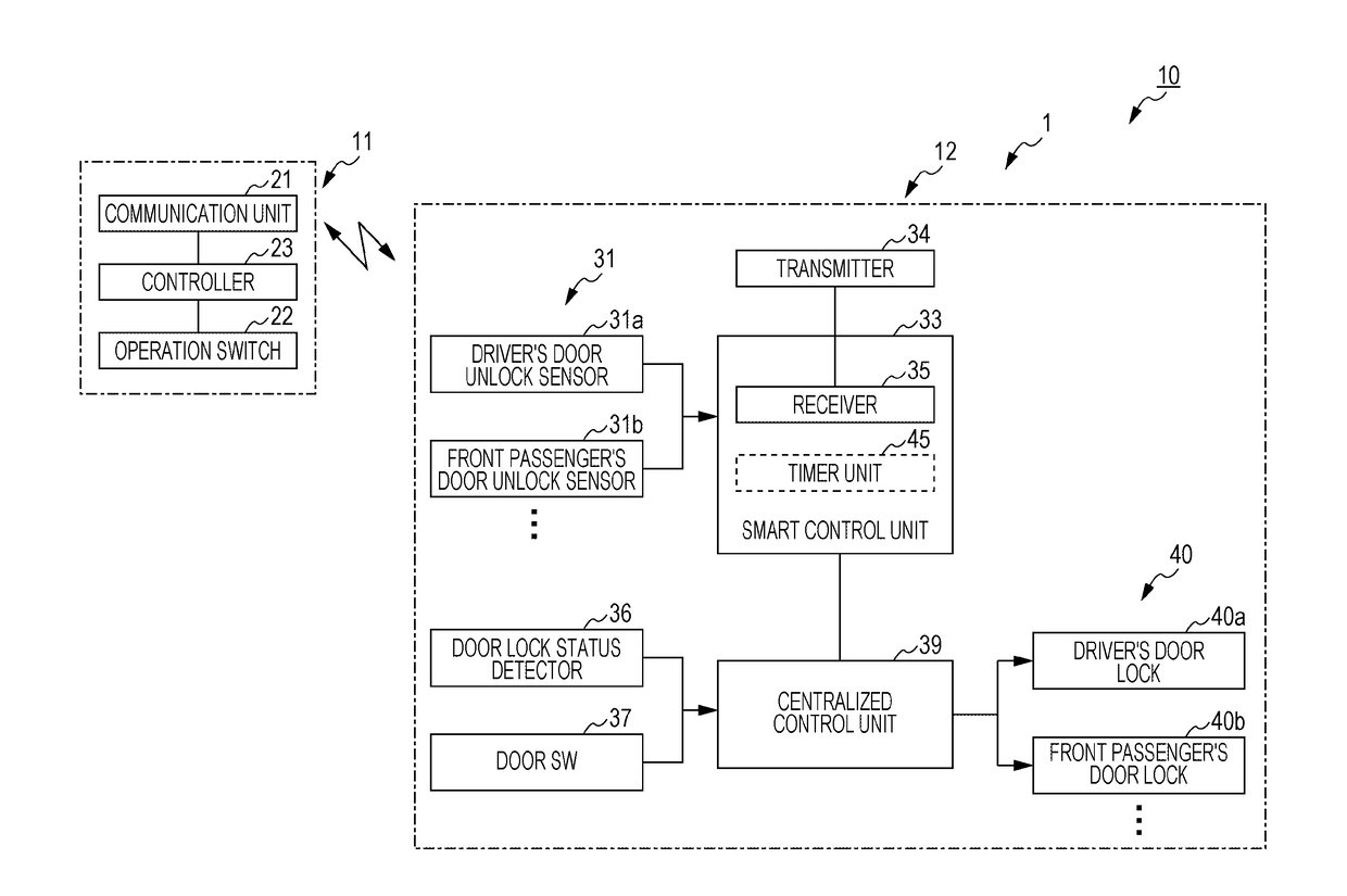
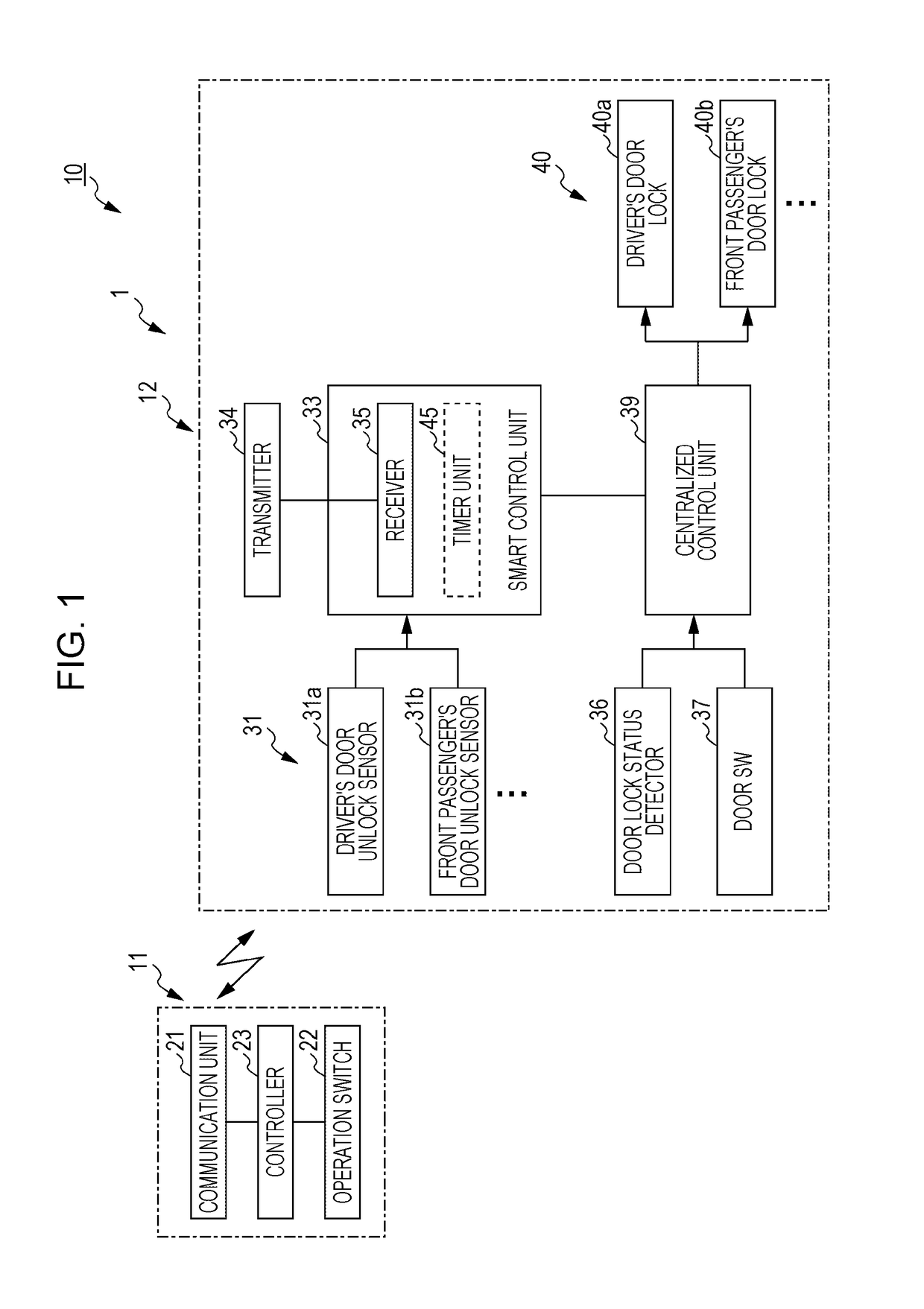
[0022]FIG. 1 is a block diagram of a smart entry system 10.

[0023]The smart entry system 10 illustrated in FIG. 1 includes a portable device 11 functioning as an electronic key of a vehicle 1, and an on-vehicle system 12 mounted on the vehicle 1.

Portable Device

[0024]The portable device 11 is a communication terminal carried by an operator (such as a driver of the vehicle 1). The portable device 11 performs wireless communication with the on-vehicle system 12. The portable device 11 transmits a response signal in response to a request signal transmitted from the on-vehicle system 12 and a command signal that instructs certain on-vehicle equipment to operate, along with unique identification information. The portable device 11 instructs, for example, a drive source (internal combustion engine, motors, and the like) of the vehicle 1 to start or stop operation, or to lock or un...


PUM


Abstract

A smart entry system includes a smart control unit that detects whether communication with a portable device has been established, and a centralized control unit that unlocks a driver's door when a driver's door unlock operation is detected and establishment of communication with the portable device is detected. The centralized control unit includes a timer unit that measures time when a passenger's door open operation is detected or when a passenger's door open operation is detected and the fact that communication with the portable device has not been established is detected. The centralized control unit unlocks at least one of the passengers' doors along with the driver's door when a driver's door unlock operation is detected and establishment of communication with the portable device is detected while the timer unit is measuring a certain period of time.

Description

CROSS REFERENCES TO RELATED APPLICATIONS[0001]The present application claims priority under 35 U.S.C. §119 to Japanese Patent Application No. 2016-050735, filed Mar. 15, 2016, entitled “Smart Entry System.” The contents of this application are incorporated herein by reference in their entirety.BACKGROUND[0002]1. Field[0003]The present application relates to a smart entry system.[0004]2. Description of the Related Art[0005]In a smart entry system, a portable device carried by an operator (such as a driver) and an on-vehicle system mounted on a vehicle perform wireless communication to lock or unlock the doors.[0006]For security reasons, the smart entry system may adopt a configuration where the doors other than the driver's door (hereinafter referred to as the “passengers' doors”) are not unlocked in an unlocking operation. In this case, to unlock the passengers' doors, it is necessary to operate a door switch in the vehicle after unlocking the driver's door, or it is necessary for t...

Claims


Application Information

Patent Timeline
Patent Type & Authority Applications(United States)
IPC IPC(8): B60R25/01B60R25/31E05B81/54
CPCB60R25/01E05B81/54B60R21/01512B60R25/2036B60R25/31B60R25/24
Inventor SUGITA, MASASHI
Owner HONDA MOTOR CO LTD
Why Eureka
Try Eureka