Combined Passive and Active Method and Systems to Detect and Measure Internal Flaws within Metal Rails

a technology of internal flaws and passive and active methods, applied in the field of rail inspection, can solve the problems of increasing creating air gaps, and introducing false calls, so as to reduce the overall cost of the inspection process, reduce the time required, and quantify the growth of the flaw.

Active Publication Date: 2017-09-21
RAILPOD
View PDF10 Cites 36 Cited by
  • Summary
  • Abstract
  • Description
  • Claims
  • Application Information

AI Technical Summary

Benefits of technology

[0041]When x-ray images are captured, they may be analyzed by a human and / or by automated image processing software. The software is capable of quantifying the growth of the flaw using border detection techniques, image comparisons techniques, and other image processing technologies. This software improves the ability for the track inspector to identify areas of interest and minimize the amount of time required to qualify the type and size of flaw. This assessment can be conducted on the inspection vehicle itself or may be conducted remotely leveraging cellular or wifi communications.
[0042]Joints and welds historically have had high failure rates in the industry. Because the magnetometers can sense welds and joints, this information can be used in vehicle positioning automation allowing the vehicle to stop and conduct inspections at specific locations where welds and joints exist. This position automation feature allows the inspection vehicle to stop and inspect at every joint or weld regardless if the internal rail flaw technology detects a variation or flaw. This inspection method allows for close monitoring of track work that typically has high failure rates and where existing technology may fail to detect that a flaw even exists.

Problems solved by technology

Additionally, the use of “couplant” to ensure no air gap between the rail and the ultrasound transducer limits use of the ultrasound system in freezing temperatures where the couplant would freeze, creating air gaps, and introducing “false calls”.
Additionally a human is required to operate the truck which increases the overall cost of the inspection process reducing the likelihood of frequent inspections that would allow for the system to track and monitor the progression of the flaw itself.
The combination of large rectifier packs, requiring a large rail bound vehicle, and only one method to inspect, restricts the ability to minimize false calls and may require a secondary inspection method to confirm the signal received by the magnetic field detector imposing time restrictions on the inspection process.
This change in mechanical structure may have short or long term impact resulting in the rail being more sensitive to rolling contact fatigue, engine burn, and other related surface flaws potentially reducing the life cycle of the rail.

Method used


Image

  • Combined Passive and Active Method and Systems to Detect and Measure Internal Flaws within Metal Rails
  • Combined Passive and Active Method and Systems to Detect and Measure Internal Flaws within Metal Rails
  • Combined Passive and Active Method and Systems to Detect and Measure Internal Flaws within Metal Rails

Examples


Embodiment Construction

[0062]Terminology

[0063]The terminology and definitions of the prior art are not necessarily consistent with the terminology and definitions of the current disclosure. Where there is a conflict, the following definitions apply.

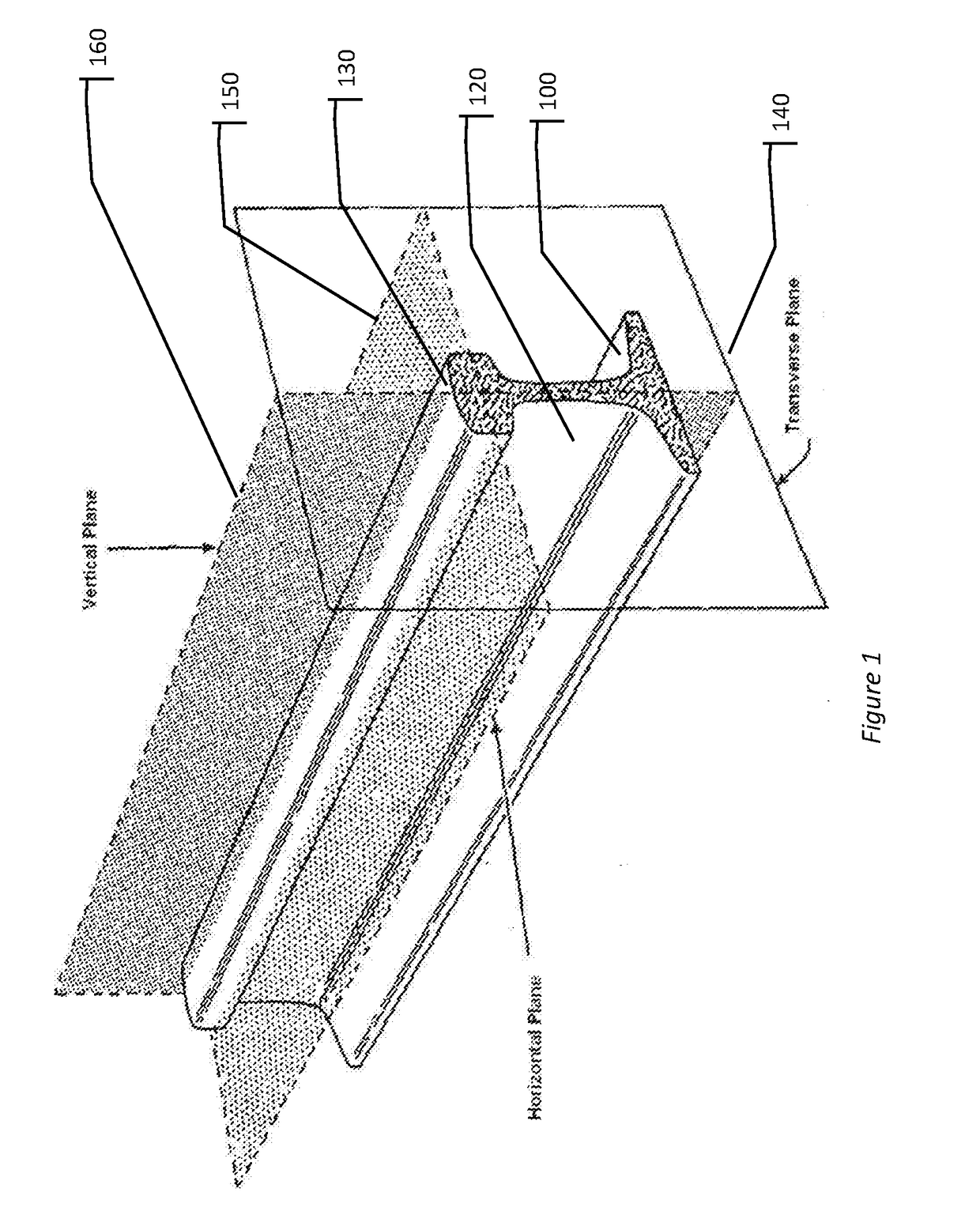
[0064]Field side—The side of the rail(s) pointing away from the track or the outside face.

[0065]Gauge side—The side of the rail which guides the wheel flange.

[0066]Parallel rails—One railroad track consists of two parallel rails. Standard gauge railroad track has two parallel rails that are separated by approximately 4 feet, 8.5 inches. Other railway gauges exist and may be greater than or less than standard gauge.

[0067]Railroad Track—Consists of two parallel rails, normally made of steel, secured to crossbeams called railroad ties or sleepers.

[0068]Frog—A crossing of point of two rails, usually as a common crossing or V-crossing.

[0069]This can be assembled out of several appropriately cut and bent pieces of rail or can be a single casting. A frog forms part of...


PUM

PropertyMeasurementUnit
distanceaaaaaaaaaa
magnetic fieldaaaaaaaaaa
speedsaaaaaaaaaa

Abstract

This invention utilizes two sensing technologies in combination with or in isolation of an automated inspection vehicle to conduct inspections of internal rail flaws in steel railroad track. A vehicle equipped with X-radiation sensing is used as a secondary method to assess the deviations in magnetic fields that are sensed by a primary sensor consisting of a single or multiple magnetometers. The magnetometers sense changes in magnetic field that are correlated to the flaws inside the steel rail. The combination of technologies improves the probability to detect railroad flaws and offers the ability to accurately track and monitor flaws.

Description

CROSS-REFERENCE TO RELATED APPLICATIONS[0001]This utility patent application claims priority from U.S. provisional patent application serial number 62 / 311,061, filed Mar. 21, 2016, titled “Combined Passive and Active Method to Detect and Measure Internal Flaws within Metal Rails” naming inventors Brendan English, Paul Sandin, Wesley Kriener, Sam Dahlberg, and Stephen Imsong.COPYRIGHT NOTICE[0002]A portion of the disclosure of this patent document contains material that is subject to copyright protection. The copyright owner has no objection to the facsimile reproduction by anyone of the patent document or the patent disclosure, as it appears in the Patent and Trademark Office patent file or records, but otherwise reserves all copyright rights whatsoever. Copyright 2017 RailPod, Inc.BACKGROUND[0003]Field of Technology[0004]This disclosure relates rail inspection, and more specifically to non-destructively detecting internal or other flaws, such as cracks or breaks, in metal rails whe...

Claims


Application Information

Patent Timeline
Patent Type & Authority Applications(United States)
IPC IPC(8): B61L3/02G01N23/18G01S17/02G01N27/82
CPCB61L3/02G01N27/82G01N2223/316G01S17/02G01N2223/646G01N23/18B61L23/042B61L23/045G01N27/83G01M5/0025G01M5/0033G01M5/0075G01M5/0083G01M5/0091G01N23/16G01N23/083
Inventor ENGLISH, BRENDANSANDIN, PAULKRIENER, WESLEYDAHLBERG, SAMIMSONG, STEPHEN
Owner RAILPOD
Why Eureka
Try Eureka