Improved dircet expansion evaporator based chiller system

a chiller system and expansion evaporator technology, applied in refrigeration machines, superheaters, lighting and heating apparatus, etc., can solve the problems of reducing the performance of air conditioning and refrigeration systems that employ modern flooded type evaporators, affecting the efficiency of air conditioning and refrigeration systems, and difficult to achieve the viscosity requirements of oil-refrigerant mixtures

Inactive Publication Date: 2017-09-21
CARRIER CORP
View PDF12 Cites 6 Cited by
  • Summary
  • Abstract
  • Description
  • Claims
  • Application Information

AI Technical Summary

Problems solved by technology

Although the lubricant is normally not useful within the system other than in the compressor, its presence in low concentrations in the system does not generally detract from the flow, heat transfer, and properties of the refrigerant as it passes through the system in a conventional vapor compression cycle.
Due to their higher miscibility, these new “wet refrigerants” tend to absorb significant amounts of oil making the viscosity requirements of the oil-refrigerant mixture difficult to achieve.
Use of immiscible oil, which does not mix with these refrigerants will improve the viscosity of the oil; however, at the same time use of immiscible oil significantly and permanently reduces the performance of air conditioning and refrigeration systems that employ modern flooded type evaporators.

Method used


Image

  • Improved dircet expansion evaporator based chiller system
  • Improved dircet expansion evaporator based chiller system
  • Improved dircet expansion evaporator based chiller system

Examples


Embodiment Construction

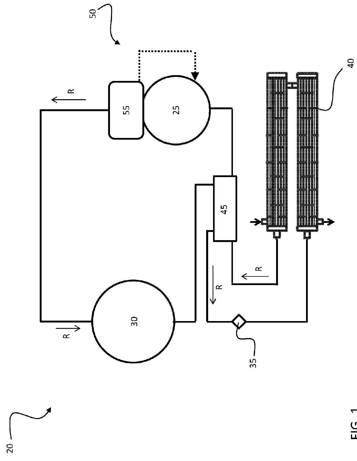
[0032]Referring now to the FIGS., an improved chiller refrigeration system 20 configured for use with either a miscible or immiscible oil is illustrated. A refrigerant R is configured to circulate through the chiller system 20 such that the refrigerant R absorbs heat when evaporated at a low temperature and pressure and releases heat when condensed at a higher temperature and pressure. In one embodiment, the refrigerant has a low global warming potential, such as a Hydrofluoroolefin (HFO) or an HFO blend refrigerant for example. Within this chiller system 20, the refrigerant R flows in a counterclockwise direction as indicated by the arrows. The compressor 25 receives refrigerant vapor from the evaporator 40 and compresses it to a higher temperature and pressure, with the relatively hot vapor then passing to the condenser 30 where it is cooled and condensed to a liquid state by a heat exchange relationship with a cooling medium, such as air or water for example. The liquid refrigera...


PUM


Abstract

A chiller system is provided including a vapor compression circuit consisting of a fluidly coupled compressor, condenser, expansion valve, and evaporator. A refrigerant circulates through the vapor compression circuit. The evaporator is a direct exchange heat exchanger. Refrigerant provided at an outlet of the evaporator is a two-phase mixture including liquid refrigerant and vapor refrigerant. The vapor refrigerant comprises less than or equal to 85% of the two-phase mixture. A refrigerant to refrigerant heat exchanger is fluidly coupled to the circuit. The refrigerant to refrigerant heat exchanger is configured to convert the vapor refrigerant provided at the outlet of the evaporator into a superheated vapor.

Description

BACKGROUND OF THE INVENTION[0001]The invention relates generally to air conditioning and refrigeration systems and, more particularly, to an air conditioning and refrigeration system that enables the use of immiscible oil.[0002]In a vapor compression system, refrigerant vapor from an evaporator is drawn in by a compressor, which then delivers the compressed refrigerant to a condenser (or a gas cooler for transcritical applications). In the condenser, heat is exchanged between a secondary fluid, such as air or water, and the refrigerant. From the condenser, the refrigerant, typically in a liquid state passes to an expansion device, where the refrigerant is expanded to a lower pressure and temperature before being provided to the evaporator. In air conditioning applications, heat is exchanged within the evaporator between the refrigerant and air or another secondary fluid, such as water, glycol, or brine for example, to condition the indoor air of a space.[0003]Since the refrigerant c...

Claims


Application Information

Patent Timeline
Patent Type & Authority Applications(United States)
IPC IPC(8): F25B40/06F25B41/00F25B1/00F25B43/02
CPCF25B40/06F25B43/02F25B2341/0012F25B1/00F25B2400/23F25B41/00F25B40/00
Inventor RAHHAL, CHARBELLORD, RICHARD G.ESFORMES, JACK LEON
Owner CARRIER CORP
Why Eureka
Try Eureka