
Optimization of distributed wi-fi networks

a distributed wi-fi and network optimization technology, applied in the direction of wireless communication, network traffic/resource management, electrical equipment, etc., can solve the problems of increasing the workload of wi-fi, real-time media applications, and many consumers still experience difficulties with wi-fi, etc., to maximize the excess capacity, maximize the capacity, and maximize the effect of an objective function

Active Publication Date: 2017-09-21
PLUME DESIGN INC
View PDF6 Cites 19 Cited by
  • Summary
  • Abstract
  • Description
  • Claims
  • Application Information

AI Technical Summary

Benefits of technology

The patent describes a method for optimizing access points in a Wi-Fi system using a cloud controller. The method takes into account factors like traffic load, signal strength, data rate, packet error rates, and network interferers to determine which access point each Wi-Fi client device should connect to. The objective is to maximize excess capacity for each load ratio. The method can be applied to individual access points or multiple Wi-Fi systems. The optimized system has a tree structure with multiple nodes and utilizes multi-path Transmission Control Protocol (TCP) for communication between parents. The method can also include hysteresis thresholds for the output. The technical effect of the patent is to improve the performance and efficiency of Wi-Fi systems by optimizing access points and utilizing network resources effectively.

Problems solved by technology

Despite Wi-Fi's popularity and ubiquity, many consumers still experience difficulties with Wi-Fi.
The challenges of supplying real-time media applications, like those listed above, put increasing demands on the throughput, latency, jitter, and robustness of Wi-Fi.
However, despite the Internet arriving reliably and fast to the edge of consumer's homes, simply distributing the connection across the home via Wi-Fi is much less reliable leading to poor user experience.
Several issues prevent conventional Wi-Fi systems from performing well, including i) interference, ii) congestion, and iii) coverage.
When two networks within range of each other carry high levels of traffic, they interfere with each other, reducing the throughput that either network can achieve.
When several demanding applications are running, such as high definition video streams, the network can become saturated, leaving insufficient capacity to support the video streams.
In many environments, such as residences, reliable Wi-Fi service cannot be obtained in all rooms.
Even if a basic connection can be obtained in all rooms, many of those locations will have poor performance due to a weak Wi-Fi signal.
Various objects in a residence such as walls, doors, mirrors, people, and general clutter all interfere and attenuate Wi-Fi signals leading to slower data rates.
However, this approach is limited by both regulatory limits on the allowed transmit power, and by the fundamental laws of nature.
The difficulty of making such a powerful access point, whether by increasing the power, or increasing the number of transmit and receive antennas, grows exponentially with the achieved improvement.
Therefore, despite the huge difficulty and expense to gain 12 dB of link budget, the resulting system may not be able to transmit through even one additional wall.
Any coverage holes that may have existed will still be present, devices that suffer poor throughput will still achieve relatively poor throughput, and the overall system capacity will be only modestly improved.
In addition, this approach does nothing to improve the situation with interference and congestion.
In fact, by increasing the transmit power, the amount of interference between networks actually goes up.
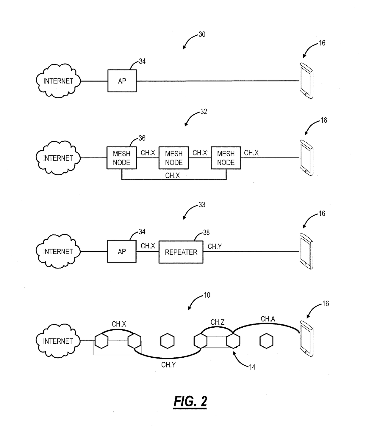
State of the art mesh or repeaters systems still have many limitations.
This creates a severe system capacity problem.
In all, the use of three hop repeating has reduced the network capacity by a factor of three.
And, as with the case of a single access point, the repeater or mesh approach does nothing to help with the problems of interference or congestion.
As before, the technique actually increases interference, as a single packet transmission becomes three separate transmissions, taking a total of 3× the airtime, generating 3× the interference to neighboring Wi-Fi networks.

Method used


Image

  • Optimization of distributed wi-fi networks
  • Optimization of distributed wi-fi networks
  • Optimization of distributed wi-fi networks

Examples


Embodiment Construction

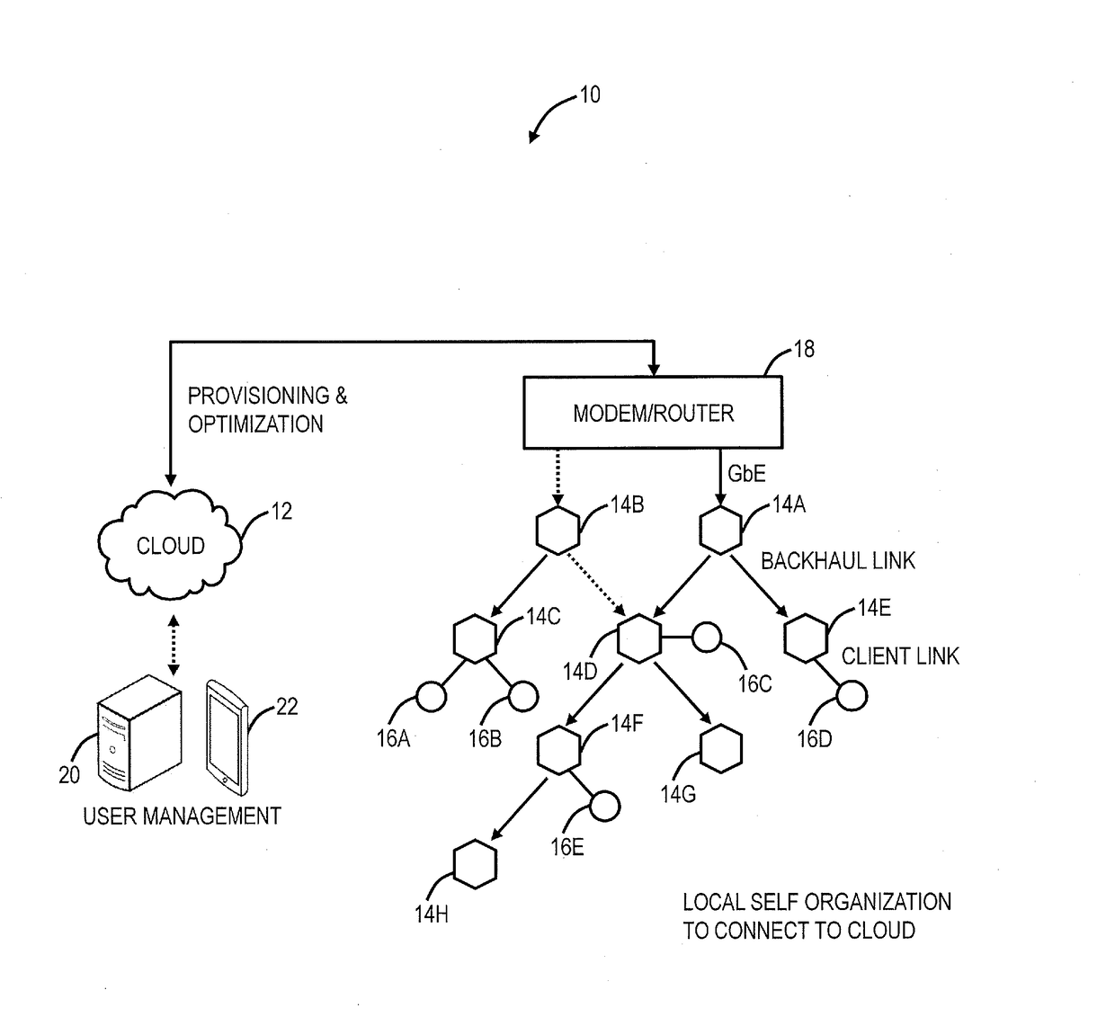
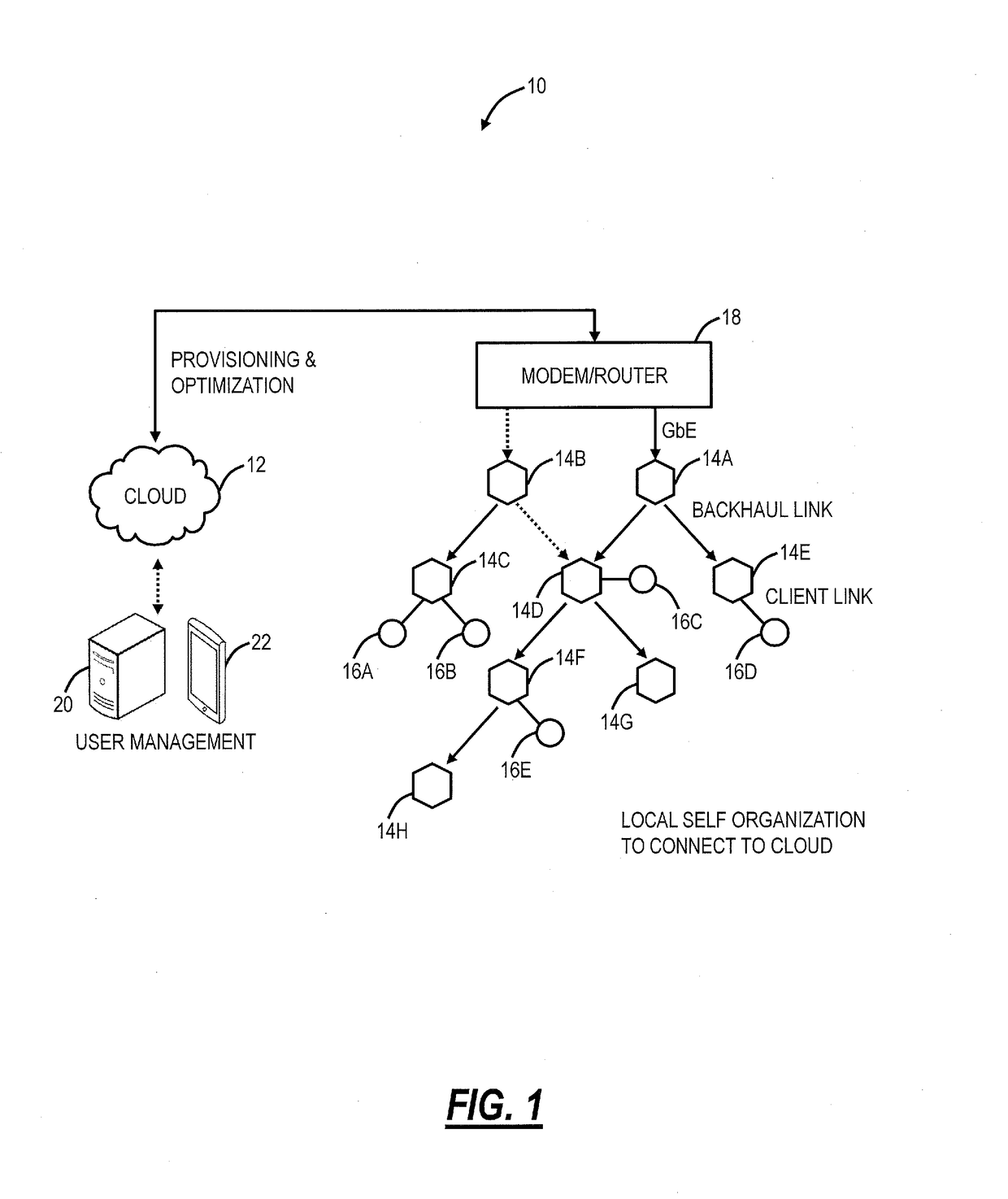
[0027]Again, in various exemplary embodiments, the present disclosure relates to data gathering systems and methods to enable the optimization of distributed Wi-Fi networks. It is an objective of the systems and methods to provide a Wi-Fi network with superior performance relative to Wi-Fi networks with a single AP, with repeaters, or with multiple mesh nodes. The systems and methods include a distributed Wi-Fi system with a plurality of access points (nodes) which are self-optimizing based on cloud-based control. This self-optimization adapts the topology and configuration of the plurality of access points in real-time based on the operating environment. The plurality of access points communicate with one another via backhaul links and to Wi-Fi client devices via client links, and the each of the backhaul links and each of the client links may use different channels based on the optimization, thereby avoiding the aforementioned limitations in Wi-Fi mesh or repeater systems. In an e...


PUM


Abstract

Systems and methods for optimization of access points in a Wi-Fi system by a cloud controller include receiving inputs related to operation of the Wi-Fi system; performing an optimization based on the inputs to maximize an objective function which maximizes excess capacity for a load ratio considering a load desired by each Wi-Fi client device; and providing outputs comprising operational parameters for the Wi-Fi system based on the optimization. The optimization chooses which access point each Wi-Fi client device connects to in the Wi-Fi system.

Description

CROSS-REFERENCE TO RELATED APPLICATION(S)[0001]The present patent / application claims priority to U.S. Provisional Patent Application No. 62 / 310,596, filed Mar. 18, 2016, and entitled “OPTIMIZATION OF DISTRIBUTED WI-FI NETWORKS,” the contents of which are incorporated by reference.FIELD OF THE DISCLOSURE[0002]The present disclosure generally relates to wireless networking systems and methods. More particularly, the present disclosure relates to optimization systems and methods in a distributed Wi-Fi system.BACKGROUND OF THE DISCLOSURE[0003]Wi-Fi networks (i.e., Wireless Local Area Networks (WLAN) based on the IEEE 802.11 standards) have become ubiquitous. People use them in their homes, at work, and in public spaces such as schools, cafes, even parks. Wi-Fi provides great convenience by eliminating wires and allowing for mobility. The applications that consumers run over Wi-Fi is continually expanding. Today people use Wi-Fi to carry all sorts of media, including video traffic, audio...

Claims


Application Information

Patent Timeline
Patent Type & Authority Applications(United States)
IPC IPC(8): H04W24/02H04W28/02
CPCH04W24/02H04W84/12H04W28/02
Inventor RENGARAJAN, BALAJIMCFARLAND, WILLIAMGAO, QINGHAI
Owner PLUME DESIGN INC
Learn More