
Grinding wheel

Active Publication Date: 2017-09-28
FICAI PAOLO
View PDF6 Cites 2 Cited by
  • Summary
  • Abstract
  • Description
  • Claims
  • Application Information

AI Technical Summary

Benefits of technology

The solution described in this patent text allows the abrasive grinding wheel to damp vibrations during use, improving user comfort and durability. The damping element can be easily and cost-effectively manufactured and bonded to the abrasive material using resin. The layered structure of the grinding wheel is compact and long-lasting. The damping element can be positioned to maximize the damping effect without increasing the axial volume of the grinding wheel. The damping element can have a similar diameter to the mounting flange of the grinding wheel, reducing vibration transmission to the grinding machine and the user. The solution also allows for the manufacturing of a damped and abrasive grinding wheel in a single piece, reducing production costs.

Problems solved by technology

High-performing (in terms of removal of material) abrasive grinding wheels generally have abrasive grains that are particularly tenacious and large and a high weight percentage of resin.
A drawback encountered in these high-performance abrasive grinding wheels lies in the fact that these grinding wheels have a very rigid structure, lacking in any kind of flexibility, a fact which, taken in combination with the high rotation velocity imparted by the work tool and the shape and balancing imperfections, leads to transmission of annoying vibrations that are damaging and fatiguing to the upper limbs of the user.

Method used


Image

  • Grinding wheel
  • Grinding wheel
  • Grinding wheel

Examples


Embodiment Construction

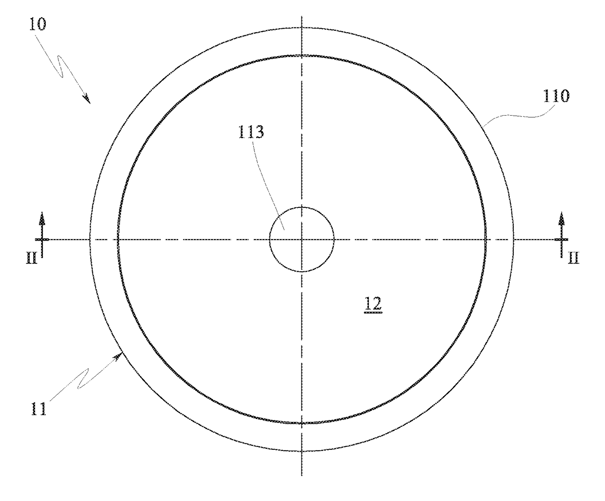
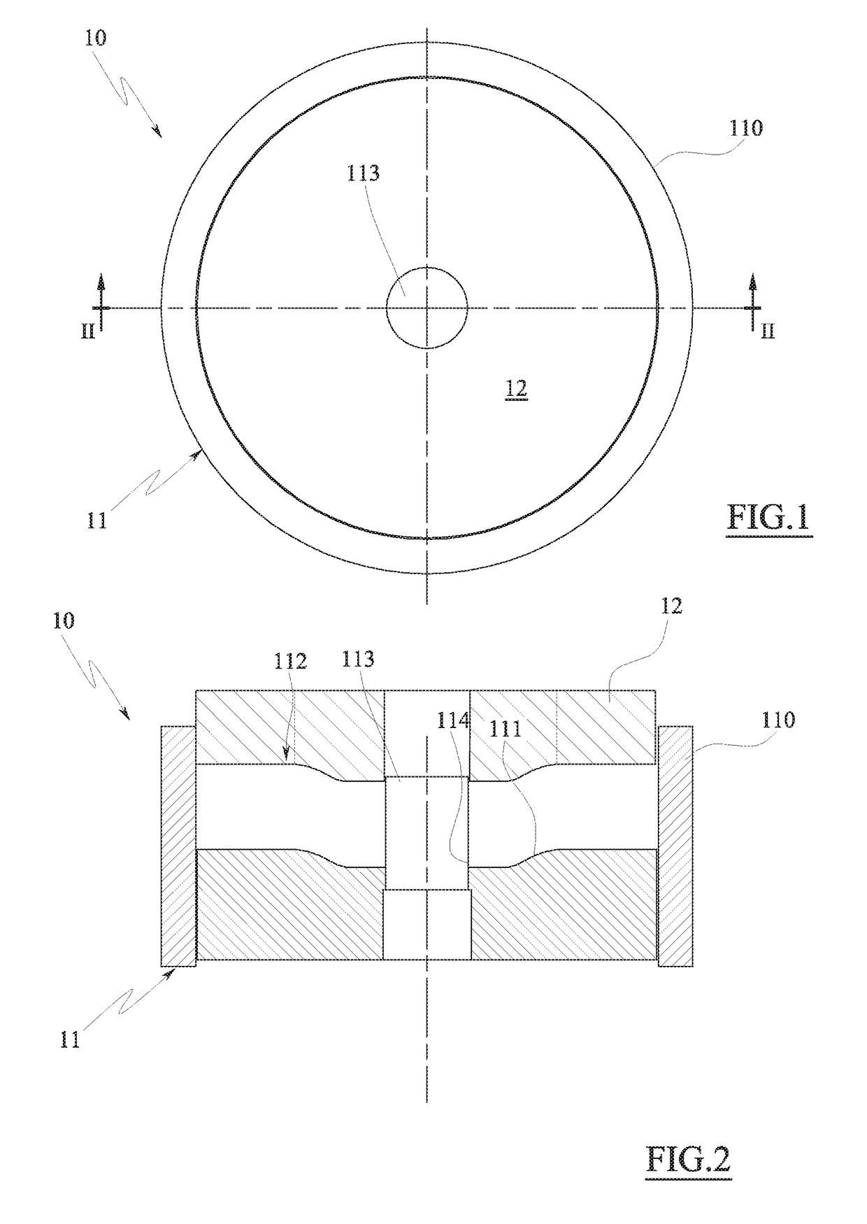
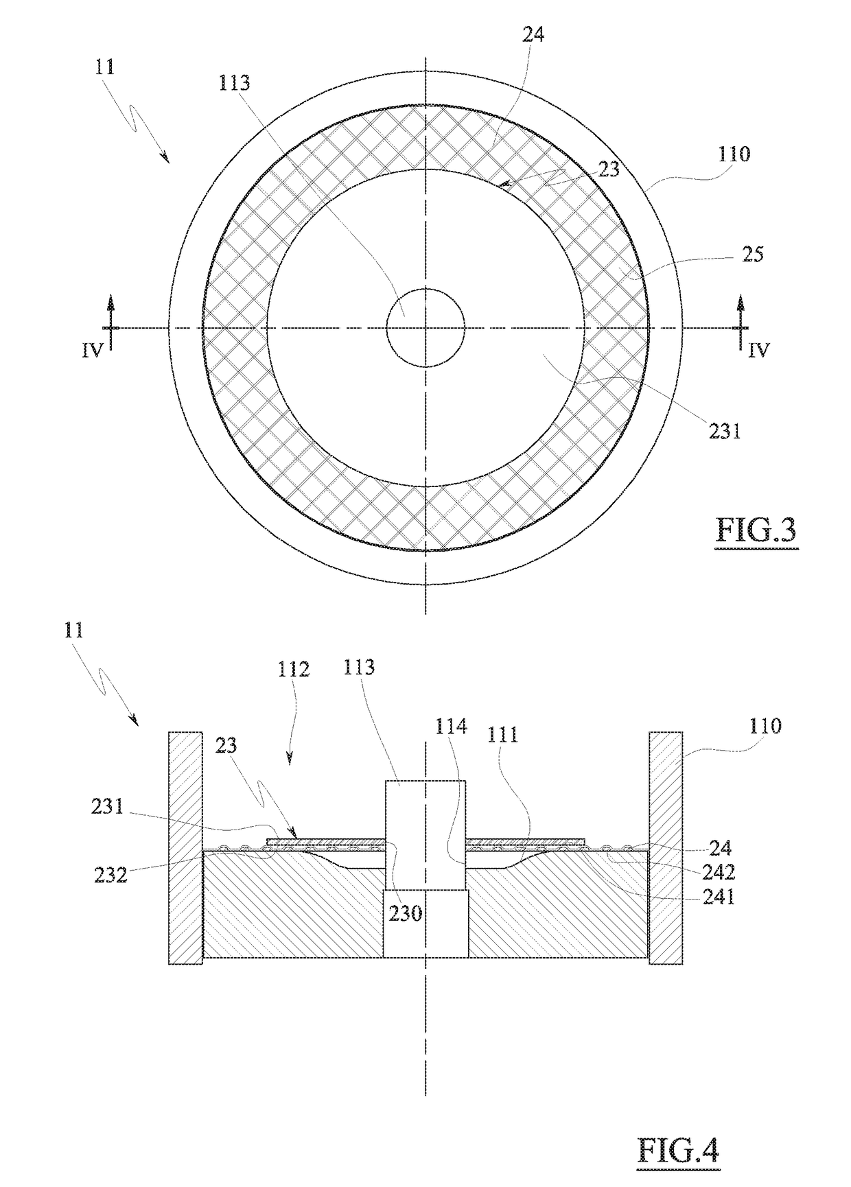
[0016]The invention in particular relates to an abrasive grinding wheel comprising an annular body having an abrasive front face at least partly made of a layer of an abrasive mixture and an opposite rear face, which grinding wheel comprises an annular damping element made of a resilient yielding material and (fixed to) incorporated in the annular body, wherein the damping element comprises a first face facing towards the abrasive front face and an opposite free second face which defines at least a portion of the rear face of the annular body.

[0017]With this solution, the abrasive grinding wheel, irrespective of the hardness of the abrasive mixture and the dimension of the abrasive grains, is able to at least partly damp the vibrations due to the contact between the abrasive grinding wheel and the piece to be machined during use of the grinding wheel itself, with undoubted advantages in terms of comfort for the user, duration of use and abrasive capacity.

[0018]In a further aspect of...


PUM


Abstract

An abrasive grinding wheel (20) comprising an annular body (200) defining an abrasive front face (202) at least partly made of a layer of an abrasive mixture (21) and an opposite rear face (203), which grinding wheel (20) comprises an annular damping element (23) made of a resilient yielding material and fixed to the annular body (200), wherein the damping element (23) comprises a first face (231) facing towards the abrasive front face (202) and an opposite free second face (232) which defines at least a portion of the rear face (203) of the annular body (200).

Description

TECHNICAL FIELD[0001]The present invention relates to an abrasive grinding wheel, having a depressed centre or flat, for grinding or cutting.PRIOR ART[0002]As is known, many grinding wheels exist, of a disc-shaped type with a depressed centre or flat, conical, semi-flexible or rigid, particularly used on portable high-speed electric or compressed-air grinding machines (60-100 m / s peripheral velocity), also known as sanding machines, for carrying out deburring and / or cutting operations. These grinding wheels are essentially constituted by an abrasive mixture reinforced by armatures constituted by one or more textile nets, one or two annular metal elements, commonly known as washers or ferrules, which delimit the fixing hole of the grinding wheel to the shaft of the grinding machine, and possibly by a paper label or identifier commonly used, adhering to one of the two faces of the grinding wheel (usually to the convex face).[0003]The abrasive mixture is, generally, constituted by grai...

Claims


Application Information

Patent Timeline
IPC IPC(8): B24D5/14
CPCB24D5/14B24D5/04B24D7/04B24D11/04
Inventor FICAI, PAOLO
Owner FICAI PAOLO
Learn More