
Lighting fixture for drop ceilings

a technology for lighting fixtures and ceilings, applied in the field of light fixtures, can solve the problems of high labor costs, safety hazards, and difficult mounting of light fixtures, and achieve the effects of reducing installation time, saving labor costs, and reducing the amount of components

Inactive Publication Date: 2017-09-28
MCMILLAN GEORGE ERIK +1
View PDF11 Cites 0 Cited by
  • Summary
  • Abstract
  • Description
  • Claims
  • Application Information

AI Technical Summary

Benefits of technology

The recessed can-type lighting fixture with a built in electric junction box utilizing a large bezel is designed to strengthen ceiling tiles and prevent warping. The fixture forms a multi-layer strengthening system with the bezel and ceiling tile nuts, which sandwich the tile and prevent rotation. The area each nut occupies provides proper load distribution for a stable mounting system. A restraint cable may be used for safety in the event of a tile dislodging from the standard retaining matrix. The fixture reduces the number of components needed and labor and material costs. It allows for mounting in any section within a drop ceiling and provides more mounting possibilities and positions. The fixture may be directly attached with the drop-ceiling tile or attached to a support structure associated with the drop-ceiling. Overall, the fixture strengthens the drop-ceiling tile and makes it more stable and secure.

Problems solved by technology

If the recessed light fixture is not attached to the actual ceiling structure, the weight of the recessed light fixture may cause the ceiling tiles to warp over time which may pose a safety hazard.
However, the prescribed procedure is labor intensive and complex as calculations must be made in order to place the light at a desired location.
Further, if there is no adequate structural attachment point is available, it makes mounting the light fixture very difficult.
It is also expensive to purchase the proper structural housings to be utilized.
Further, it saves a lot of labor cost and material cost.

Method used


Image

  • Lighting fixture for drop ceilings
  • Lighting fixture for drop ceilings
  • Lighting fixture for drop ceilings

Examples


Embodiment Construction

[0020]All descriptions are for the purpose of showing selected versions of the present invention and are not intended to limit the scope of the present invention.

[0021]Non-limiting and non-exhaustive embodiments of the present invention are described with reference to the preceding figures, wherein like reference numerals refer to parts throughout the various views unless otherwise precisely specified.

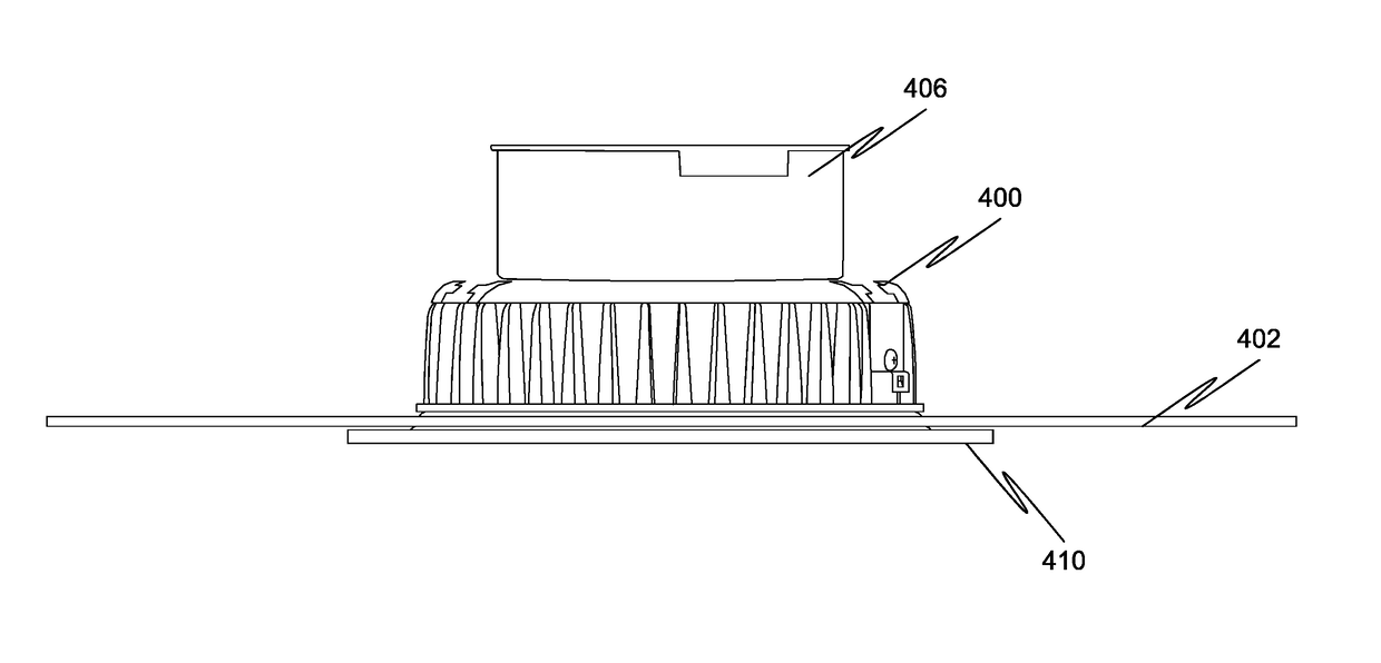
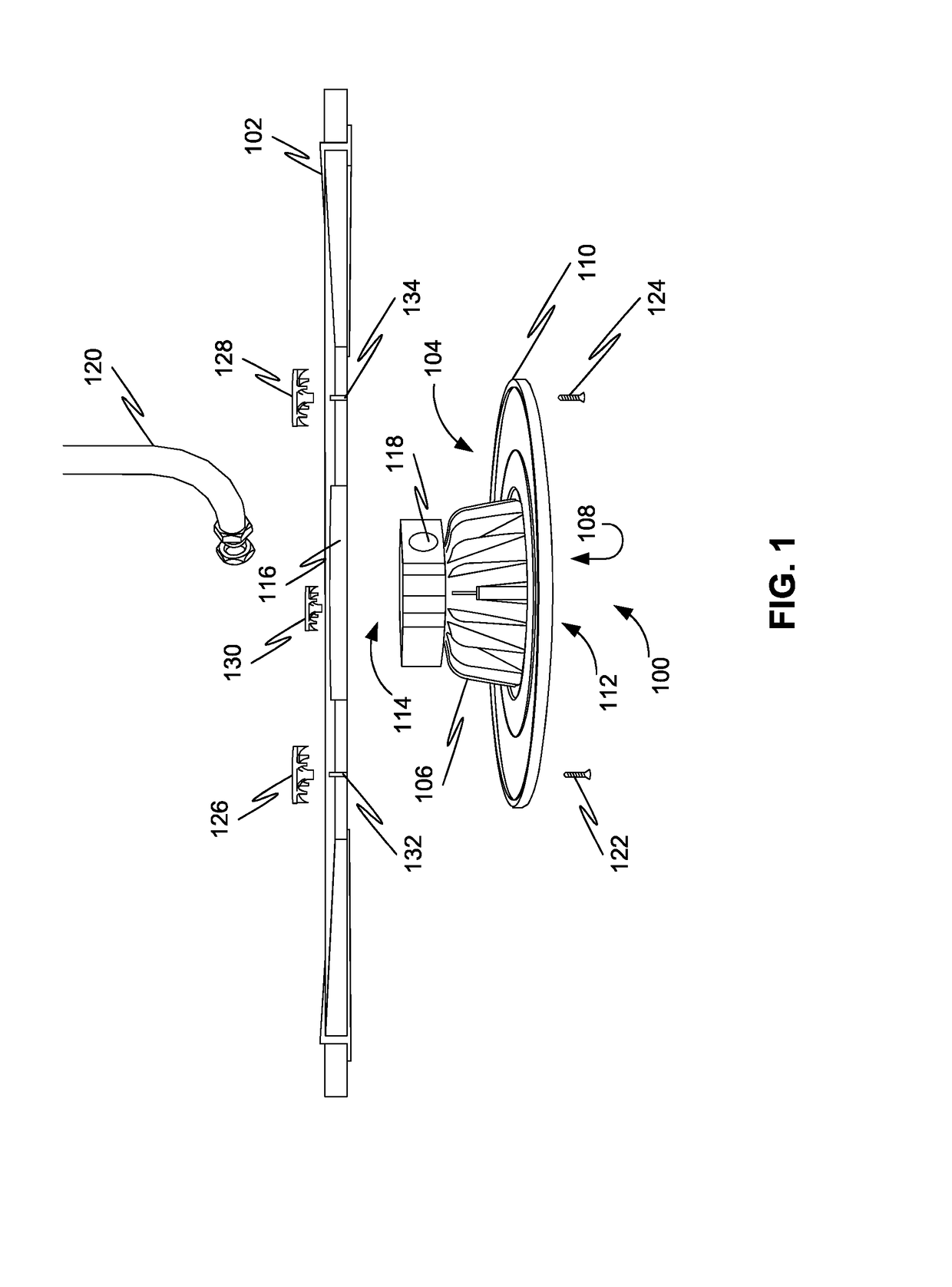
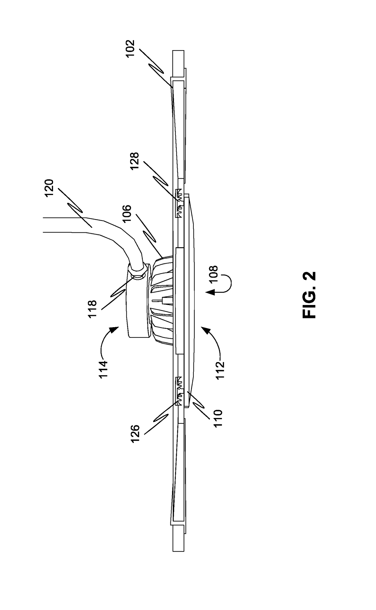
[0022]The present disclosure relates to a light fixture configured to be mounted on a drop ceiling. The light fixture may include a luminaire. The luminaire may be a can-type lighting system. The luminaire may include a body comprising a cavity configured to house one or more light sources. The luminaire may also include a socket configured to receive the one or more light sources.

[0023]Further, the luminaire may include a bezel circumferentially disposed around an opening of the cavity. The body may include a proximal portion and a distal portion, wherein the bezel may be disposed adj...


PUM


Abstract

Disclosed is a light fixture configured to be mounted on a drop ceiling. The light fixture includes a luminaire. The luminaire includes a body comprising a cavity configured to house one or more light sources. Further, the luminaire includes a bezel circumferentially disposed around an opening of the cavity. Yet further, the luminaire includes an electrical connector configured to interface with a power cable. Moreover, the luminaire includes multiple fastening members configured to fasten the bezel to a drop-ceiling tile.

Description

[0001]The current application claims a priority to the U.S. Provisional Patent application Ser. No. 62 / 321,847 filed on Apr. 13, 2016.FIELD OF THE INVENTION[0002]The present disclosure generally relates to light fixtures. More specifically, the present disclosure relates to light fixture configured to be mounted to a drop ceiling.BACKGROUND OF THE INVENTION[0003]Many commercial and residential buildings have drop ceilings. National Electrical Code (NEC) and many other standard organizations provide guidelines for incorporating light fixtures (luminaires) into drop ceilings. For example, for safety reasons when installing recessed can-type lighting, the guidelines recommend that a complete recessed light fixture must be safely attached above the drop ceiling and secured to the actual ceiling above drop ceiling structure. If the recessed light fixture is not attached to the actual ceiling structure, the weight of the recessed light fixture may cause the ceiling tiles to warp over time...

Claims


Application Information

Patent Timeline
Patent Type & Authority Applications(United States)
IPC IPC(8): F21V21/04F21V23/06F21S8/02
CPCF21V21/041F21V23/06F21S8/026
Inventor MCMILLAN, GEORGE ERIKLOHR, PETER JAMES
Owner MCMILLAN GEORGE ERIK
Learn More