Illumination device

a technology of illumination device and heat sink, which is applied in the direction of lighting and heating apparatus, lighting support devices, fixed installations, etc., can solve the problems of adversely affecting the performance and lifetime of illumination devices, and achieve the effects of efficient dissipation, low cost, and reduced weight of heat sinks

Inactive Publication Date: 2017-09-28
SAMSUNG ELECTRONICS CO LTD
View PDF8 Cites 5 Cited by
  • Summary
  • Abstract
  • Description
  • Claims
  • Application Information

AI Technical Summary

Benefits of technology

[0023]According to the current exemplary embodiment, an illumination device having a structure by which heat generated from a light source unit or a PSU may efficiently dissipate to the outside of the illumination device is provided. The weight of a heat sink may be reduced by forming at least one of heat dissipation pins and exposing a housing or an inner space of the housing between the heat dissipation pins. Also, an illumination device that satisfies the lamp specification of the American National Standards Institute (ANSI) and a high speed dimmable illumination device are provided.

Problems solved by technology

Heat generated from a light source or a power supply unit of an illumination device may adversely affect the performance and lifetime of the illumination device.

Method used


Image

  • Illumination device
  • Illumination device
  • Illumination device

Examples


Embodiment Construction

[0039]Reference will now be made in detail to exemplary embodiments, examples of which are illustrated in the accompanying drawings, wherein like reference numerals refer to like elements throughout. In the drawings, the sizes or thicknesses of constituent elements are exaggerated for clarity.

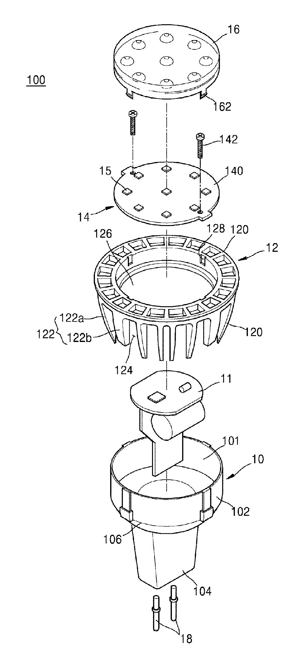
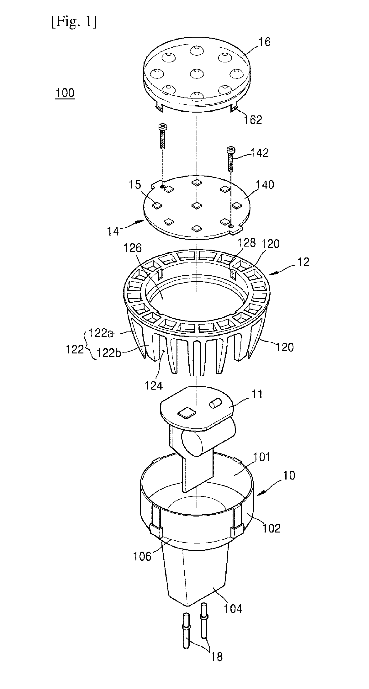
[0040]FIG. 1 is an exploded perspective view of an illumination device 100 according to an exemplary embodiment. FIG. 2 is a lateral view of the illumination device 100.

[0041]Referring to FIGS. 1 and 2, the illumination device 100 according to an exemplary embodiment may include a housing 10, a power supply unit (PSU) 11 inserted into the housing 10, and a heat sink 12 coupled to the housing 10. Also, the illumination device 100 may include a light source unit 14 that is placed on the heat sink 12 to irradiate light to the outside and a cover unit 16 that covers the light source unit 14. A terminal unit 18 to receive external power may be formed on an edge, for example, a lower side of the hous...


PUM


Abstract

An illumination device is provided. The illumination device includes a heat sink coupled to a housing, and the heat sink includes at least one heat dissipation pin extending from an external surface of the housing. Vent holes that expose the external surface of the housing, an inside of the housing, or an inside of the illumination device to external air are formed on a side of the at least one heat dissipation pin. An upper edge of the housing and the heat sink may be spaced apart from each other, and the spaced region may include a gap that exposes the illumination device or the inside of the housing.

Description

TECHNICAL FIELD[0001]The present disclosure relates to illumination devices, and more particularly, to illumination devices having at least a part of an upper edge of a housing thereof exposed.BACKGROUND ART[0002]An illumination device is generally used for securing a clear view in a dark place, expressing a visual effect of an advertisement, or having an aesthetic purpose. A light source of an illumination device may include an incandescent light, a fluorescent light, or a halogen light. In recent years, a light-emitting diode (LED) is used as a light source.[0003]An LED used in an illumination device may realize various colors of light by changing a compound semiconductor material, such as GaAs, AlGaAs, GaN, and InGaInP. LEDs have merits of having a long lifetime, being miniature and light, and low voltage driving is possible due to strong directionality of light. An illumination device that employs an LED is widely used in various fields due to its high optical efficiency, high e...

Claims


Application Information

Patent Timeline
Patent Type & Authority Applications(United States)
IPC IPC(8): F21V21/30H05B33/08F21S8/00H05B44/00
CPCF21V21/30F21Y2115/10H05B33/0896F21S8/035F21V29/74F21V29/83F21V17/16F21V23/00F21V29/777F21K9/233F21V29/00H05B45/60
Inventor YUN, HYEONG-WONLEE, WOOK-PYOKIM, SEOK-KYUJUNG, YOUNG-HO
Owner SAMSUNG ELECTRONICS CO LTD
Why Eureka
Try Eureka