
Cable jackets having designed microstructures and methods for making cable jackets having designed microstructures

a technology of microstructure and cable jacket, which is applied in the direction of insulation conductor/cable, instruments, other domestic objects, etc., can solve the problems of fibers delicate and need to be protected, and achieve the effect of higher flexural modulus

Active Publication Date: 2017-09-28
DOW GLOBAL TECH LLC
View PDF13 Cites 21 Cited by
  • Summary
  • Abstract
  • Description
  • Claims
  • Application Information

AI Technical Summary

Benefits of technology

The invention is a type of optical fiber cable that has a reinforcing layer made of a flexible plastic material. This layer contains tiny channels that enhance the cable's integrity and protect the underlying optical fibers. The overall effect is an improved strength and durability of the optical fiber cable.

Problems solved by technology

These fibers are delicate and need to be protected.

Method used


Image

  • Cable jackets having designed microstructures and methods for making cable jackets having designed microstructures
  • Cable jackets having designed microstructures and methods for making cable jackets having designed microstructures
  • Cable jackets having designed microstructures and methods for making cable jackets having designed microstructures

Examples


examples

Sample Preparation

Microcapillary Samples

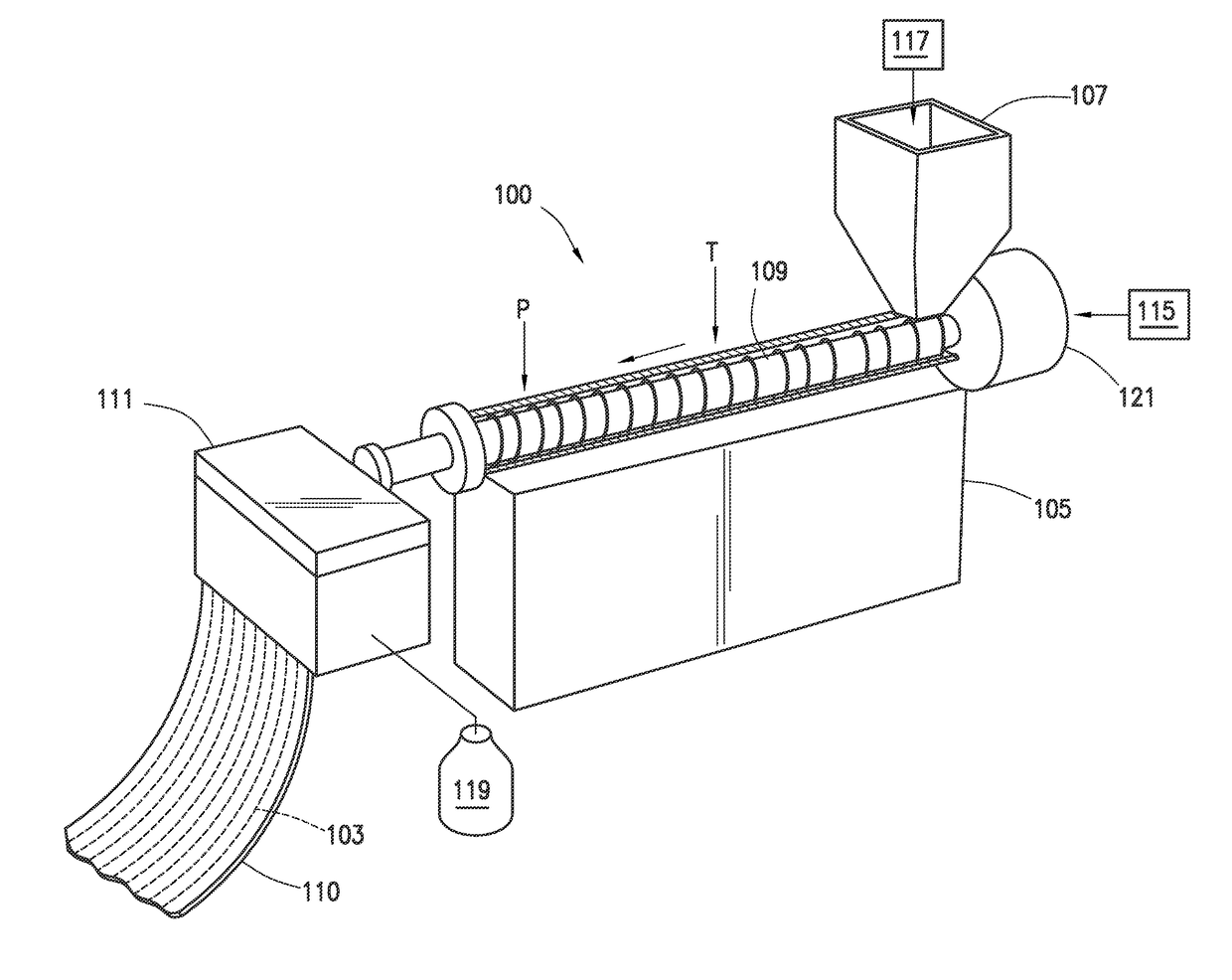
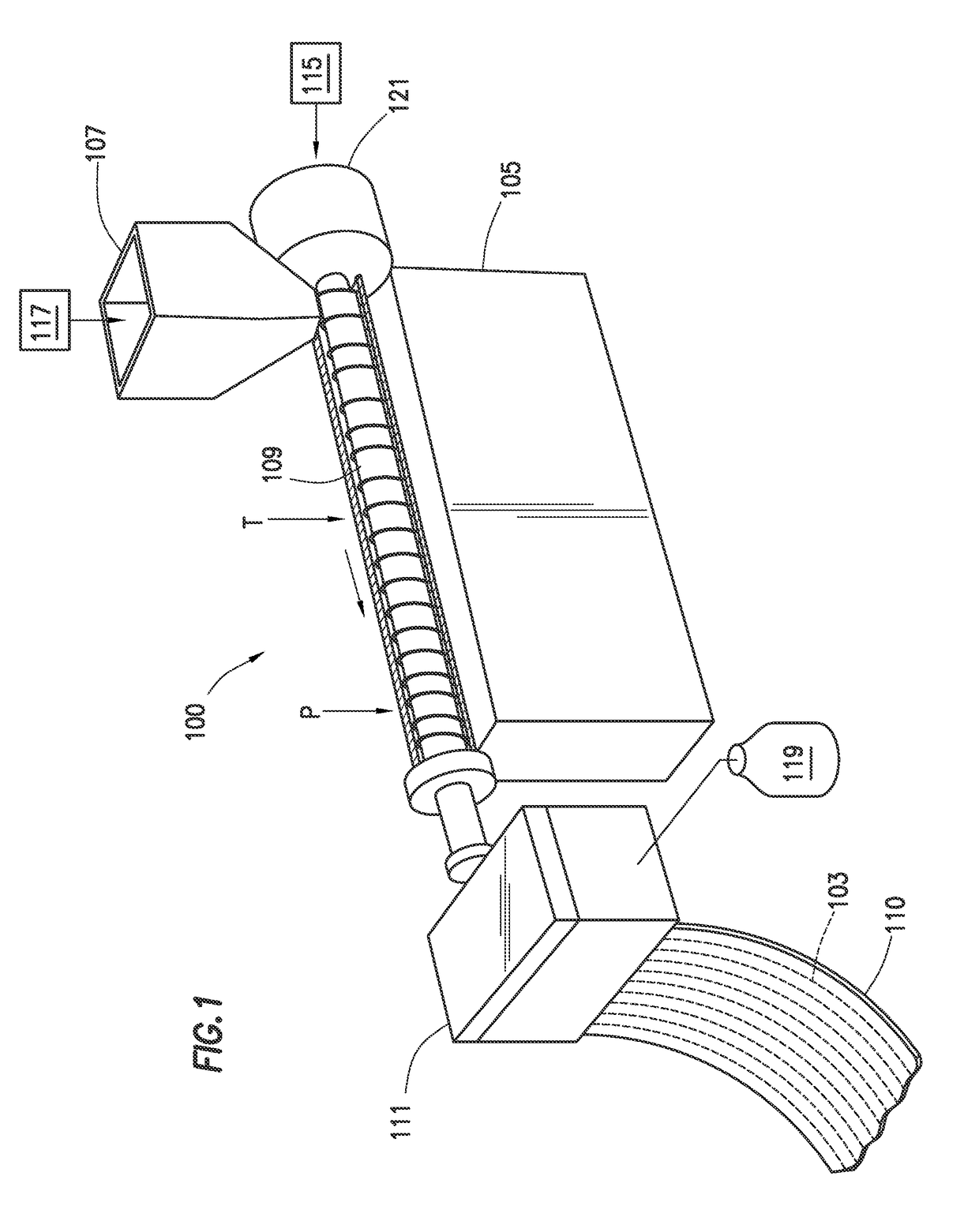
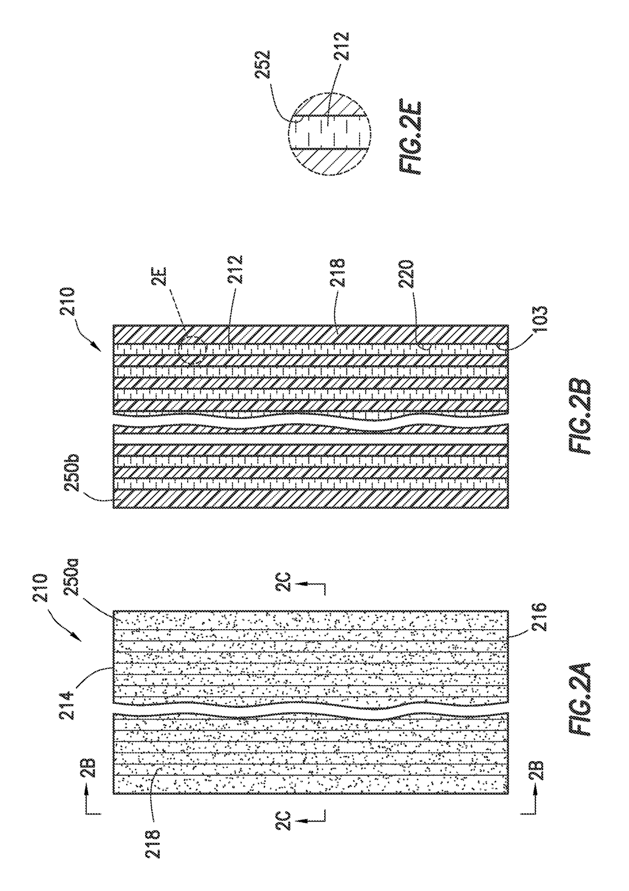
[0165]Prepare one sample (S1) and one comparative sample (CS1) using a tape-extrusion system consisting of two single-screw extruders (1.9-cm and 3.81-cm Killion extruders) fitted with a microcapillary die capable of handling two polymer melt streams. This line consists of a 3.81-cm Killion single-screw extruder to supply polymer melt for the matrix material and a 1.9-cm Killion single-screw extruder to supply polymer melt for the microcapillaries via a transfer line to the microcapillary die. The die to be used in these Examples is described in detail in PCT Published Patent Application No. WO 2014 / 003761, specifically with respect to FIGS. 4A and 4A1, and the corresponding text of the written description, which is incorporated herein by reference. The die has 42 microcapillary nozzles, a width of 5 cm, and a die gap of 1.5 mm. Each microcapillary nozzle has an outer diameter of 0.38 mm and an inner diameter of 0.19 mm.

[0166]Sample S1 and com...

example

LDPE Microcapillary Tape Analysis

[0170]Analyze each of S 1, CS1, Control 1, and Control 2 according to the Test Methods provided above. The results are provided in Table 4, below.

TABLE 4Properties of Control 1, Control 2, CS1, and S1Control 1Control 2(HDPE)(PBT)CS1S1Density (g / cm3)0.9451.3040.9861.208Tensile Strength (psi)4,0166,5242,6634,904Tensile Modulus (psi)4.22E+044.16E+058.19E+042.23E+05Shrinkback (%)0.3100.160Gel pick up after aging4.3103.590.41(%)Aged* tensile strength2,1836,8672,6146,252(psi)*As aged for gel pick up testing

[0171]As can be seen from the results provided in Table 1, S1, which employs PBT as a matrix material with HDPE as microcapillary material, shows a reduction in tensile strength and lower density (desired) compared to pure PBT (Control 2); however, S1 has a density about 1.4 times higher than HDPE (Control 1). The modulus of S1 higher than HDPE and lower versus PBT, indicating improved flexibility, and the shrinkback is typical of pure PBT and well less ...


PUM

PropertyMeasurementUnit
flexural modulusaaaaaaaaaa
temperatureaaaaaaaaaa

Abstract

Optical fiber cables (1001) comprising at least one optical fiber transmission medium (1006) and at least one elongated polymeric protective component (1002) surrounding at least a portion of the optical fiber transmission medium. The elongated polymeric protective component (1002) comprises a polymeric matrix material and a plurality of microcapillaries containing a polymeric microcapillary material, where the polymeric matrix material has a higher flexural modulus than the polymeric microcapillary material. Also disclosed are dies and methods for making such optical fiber cables and protective components.

Description

REFERENCE TO RELATED APPLICATIONS[0001]The present application claims the benefit of U.S. Provisional Application No. 62 / 094,439, filed on Dec. 19, 2014.FIELD[0002]Various embodiments of the present invention relate to cable coatings and jackets having microcapillary structures.INTRODUCTION[0003]Optical fibers efficiently transmit information at high rates and over long distances. These fibers are delicate and need to be protected. In practical application, a fiber optic cable protects the fibers from mechanical damage and / or adverse environmental conditions such as moisture exposure. For example, specific protective components include extruded buffer tubes, core tubes, and slotted core members.[0004]Buffer tubes, also known as loose buffer tubes, are protection components used to house and protect optical fibers, such as in a cable. Typically, these loose buffer tubes are filled with a hydrocarbon gel or grease to suspend and protect the fiber from moisture and have stringent requi...

Claims


Application Information

Patent Timeline
Patent Type & Authority Applications(United States)
IPC IPC(8): G02B6/44H01B13/14B29C48/05B29C48/07B29C48/19B29C48/20B29C48/21
CPCG02B6/4433G02B6/448B29C47/064B29K2077/00B29C47/065H01B13/14B29C48/07B29C48/05G02B6/443B29C48/21B29C48/20B29C48/19B29L2011/0075B29K2995/0096B29K2995/0082B29K2071/00B29K2067/003B29K2067/006
Inventor ESSEGHIR, MOHAMEDHUANG, WENYIDOOLEY, JOSEPHLEE, PATRICK CHANG DONG
Owner DOW GLOBAL TECH LLC
Learn More