
Method of manufacturing light emitting device

Active Publication Date: 2017-09-28
TOYODA GOSEI CO LTD
View PDF0 Cites 2 Cited by
  • Summary
  • Abstract
  • Description
  • Claims
  • Application Information

AI Technical Summary

Benefits of technology

This patent describes a method for making a light emitting device that can prevent problems like reduced brightness and uneven color caused by how the light spreads through the device. This method can save money and reduce the chances of certain parts of the device not working well.

Problems solved by technology

Therefore, the manufacturing cost may increase due to the complicated manufacturing process.
However, in the proposed sealing method, it is difficult to provide an equalized curing temperature for the sealing resin which is formed into a thin sheet with a large area.

Method used


Image

  • Method of manufacturing light emitting device
  • Method of manufacturing light emitting device
  • Method of manufacturing light emitting device

Examples


first embodiment

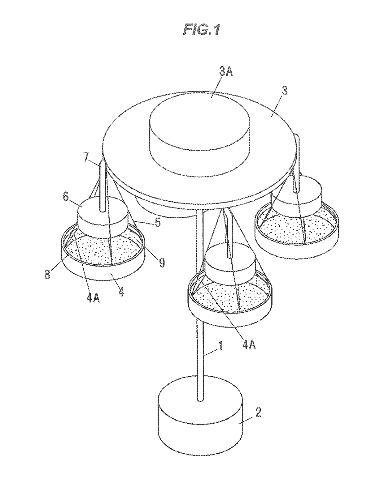
[0047]FIG. 1 is a schematic drawing of a phosphor settling device used in a method of manufacturing a light emitting device according to the first embodiment. The phosphor settling device is provided with a drive part 2 which rotates a rotational axis 1, a rotating plate 3 which is fixed on the rotational axis 1, a mold 4 which is hanged on a periphery of the rotating plate 3 through wire 5, a phosphor supplier 6 (which is provided with a nozzle (not shown)) which is disposed above the mold 4, and a hose 7 to supply phosphor from a phosphor tank 3A on the rotating plate 3 to the phosphor supplier 6.

[0048]The rotating plate 3 is rotated by receiving driving force from the drive part 2 through the rotational axis 1 in a predetermined rotating frequency.

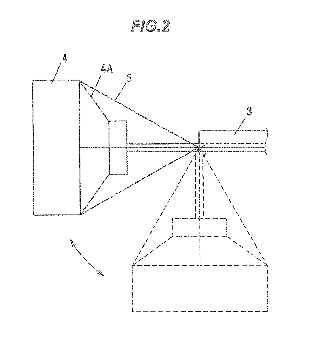
[0049]The mold 4 is connected with one end of plural wires 5 (three wires in the present embodiment) of which the other end are connected to a hanging member (not shown) of the rotating plate 3, and supported by the hanging member of th...

second embodiment

[0071]FIGS. 5A to 5F are explanation diagrams showing a light emitting device according to the second embodiment. A method of manufacturing the light emitting device according to the present embodiment is different in using a red phosphor (or reddish phosphor) and a green phosphor (or greenish phosphor) instead of the yellow phosphor used in the first embodiment. Since the heating process and the fabricating process of the light emitting device are followed by the first embodiment, a phosphor settling process will be mainly explained below.

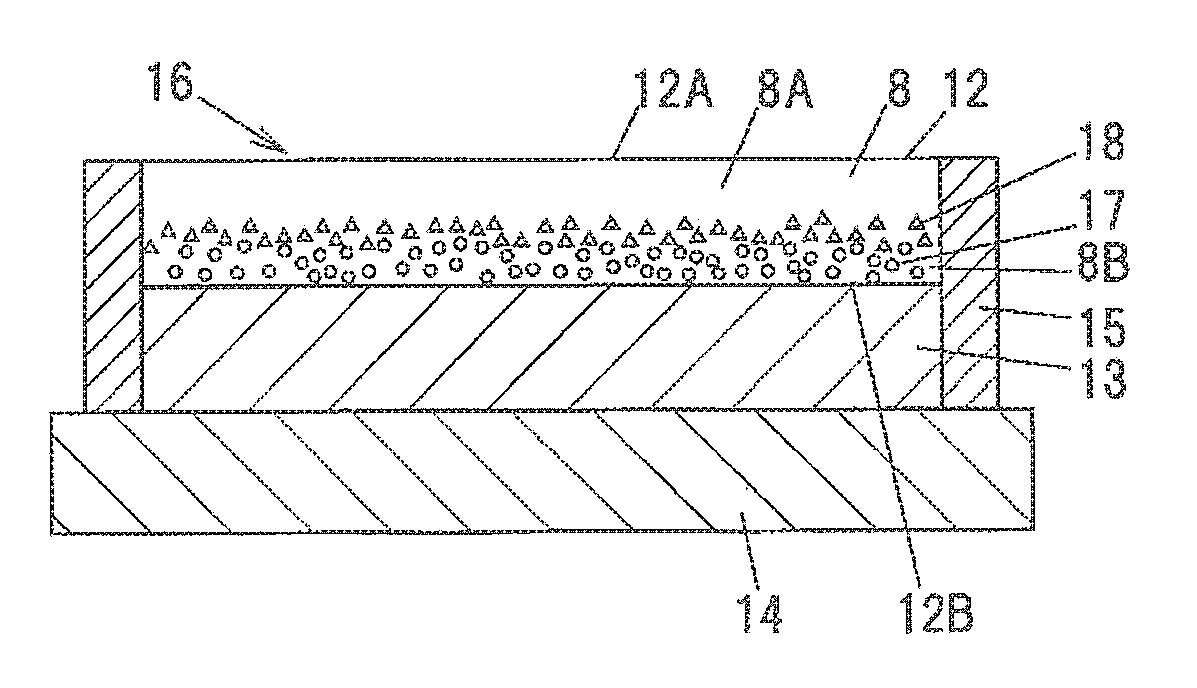
[0072]First, the transparent resin 8 having fluidity such as liquid or paste is injected into the mold 4 of the phosphor settling device shown in FIG. 1, and then the red phosphor 9 is supplied from the phosphor tank 3A of the phosphor settling device to the phosphor supplier 6 through the hose 7, and is jet evenly on the whole surface of the transparent resin 8 from above the mold 4. For example, KSF phosphor (K2SiF6:Mn) is used as the red phosph...


PUM


Abstract

A method of manufacturing a light emitting device includes injecting liquid or pasty transparent resin into a sheet forming mold, adding a phosphor to the resin in the mold, centrifugally rotating the mold so as to settle the phosphor included in the resin toward one surface side of the resin, thermally curing the resin so as to form a phosphor sheet, the phosphor sheet including a phosphor layer formed on the one surface side of the resin and a transparent layer formed on an other surface side of the resin, overlaying the phosphor sheet on a light emitting element such that the phosphor layer of the phosphor sheet contacts with a light emitting surface of the light emitting element, mounting the light emitting element with the phosphor sheet overlaid on a board, and flattening a surface of the transparent layer of the phosphor sheet on the light emitting element.

Description

[0001]The present application is based on Japanese patent application No. 2016-057609 filed on Mar. 22, 2016, the entire contents of which are incorporated herein by reference.BACKGROUND OF THE INVENTION[0002]1. Field of the Invention[0003]The invention relates to a method of manufacturing a light emitting device using a phosphor sheet.[0004]2. Description of the Related Art[0005]A light emitting device is known in which the phosphor sheet obtained by processing a phosphor containing resin into a sheet is disposed on a light emitting surface of a light emitting element such as a light emitting diode (LED) chip is known. In the light emitting device, a color of a light emitted from the light emitting element and transmitted through the phosphor sheet is mixed with a color of a light emitted from the phosphor in the phosphor sheet so as to produce an emission color of the light emitting device.[0006]In the above light emitting device, the phosphor is dispersed in a whole thickness dir...

Claims


Application Information

Patent Timeline
IPC IPC(8): H01L33/50H01L33/62
CPCH01L33/505H01L33/62H01L2933/0066H01L2933/0041H01L33/504
Inventor TOYODA, YUSUKENARITA, TAKUMIOGAWA, MASANORITANAKA, MOTOYUKI
Owner TOYODA GOSEI CO LTD
Features
  • Generate Ideas
  • Intellectual Property
  • Life Sciences
  • Materials
  • Tech Scout
  • Unparalleled Data Quality
  • Higher Quality Content
  • 60% Fewer Hallucinations
Learn More