
Omnistereo imaging

a technology of omni-stereo imaging and image processing, applied in the field ofimmersive imaging, can solve the problem that the capture cannot be done using two cameras side by side, and achieve the effect of reducing misalignmen

Active Publication Date: 2017-09-28
VALORISATION RECH LLP
View PDF3 Cites 19 Cited by
  • Summary
  • Abstract
  • Description
  • Claims
  • Application Information

AI Technical Summary

Benefits of technology

The patent describes a method for stitching together images from multiple cameras to create a seamless and immersive video. This method uses a technique called epipolar stitching to align the images from neighboring cameras, reducing misalignments caused by parallax. Additionally, the method allows for unconstrained dynamic scene capture and results in a high-resolution monocular camera setup. The video can also be displayed in a way that creates a depth perception for the viewer. Overall, this method improves the quality and experience of video capture and viewing.

Problems solved by technology

The difficulty in capturing omnistereo images is that capture cannot simply be done using two cameras side by side.

Method used


Image

  • Omnistereo imaging
  • Omnistereo imaging
  • Omnistereo imaging

Examples


Embodiment Construction

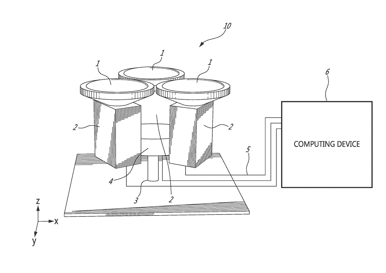
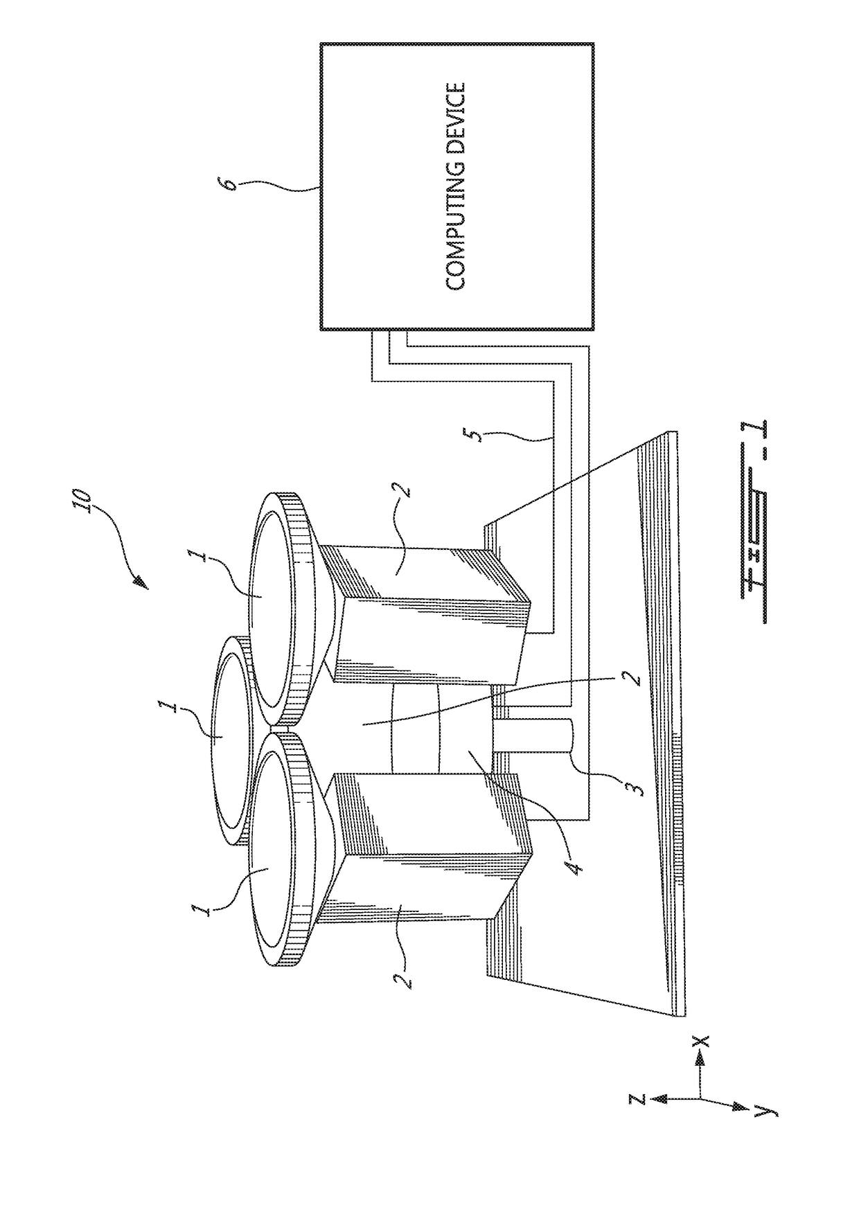
[0061]FIG. 1 illustrates an exemplary setup for an omnipolar imaging device 10. Three ultra wide angle lenses 1, such as fisheye lenses, are mounted onto three cameras 2. The cameras may be of any type on which an ultra wide angle lens can be provided in order to capture static and / or video (i.e. dynamic) images. For example, the cameras may be Prosilica 1380 cameras of 1360×1024 pixel resolution with Fujinon C-mount fisheye lenses, or Canon HFS11 cameras of 1920×1090 pixel resolution with Opteka Vortex fisheye lenses. The cameras 2 are securely fixed onto a cylindrical attachment 4 resting on a support 3. The cylindrical attachment 4 and support 3 may take various forms to ensure a known and fixed relative position of each camera 2. A single means, such as a three-camera tripod, may be used. The omnipolar imaging device 10 may face upwards, as illustrated, and capture images from the height of the lenses 1 and above, or it may be positioned with the lenses 1 facing downwards in ord...


PUM


Abstract

A method for generating a 360 degree view. N input images are captured from N cameras fixed at a baseline height equidistantly about a circle in an omnipolar camera setup where N≧3. Two epipolar lines are defined per field of view from the cameras to divide the field of view of each one of the cameras into four parts. Image portions from each one of the cameras are stitched together along vertical stitching planes passing through the epipolar lines. Regions corresponding to a visible camera are removed from the image portions using deviations performed along the epipolar lines. Output images are formed for left and right eye omnistereo views by stitching together the first one of the four parts from each one of the fields of view and the second one of the four parts from each one of the fields of view, respectively.

Description

CROSS REFERENCE TO RELATED APPLICATIONS[0001]The present application is a continuation of U.S. patent application Ser. No. 14 / 817,510 filed on Aug. 4, 2015, which is a continuation of International Application No. PCT / CA2014 / 000092, filed on Feb. 4, 2014, designating the United States, which itself claims the benefit of U.S. provisional Application Ser. No. 61 / 760,383, filed on Feb. 4, 2013, the contents of which are hereby incorporated by reference.TECHNICAL FIELD[0002]The present disclosure relates to the field of immersive imaging to obtain a 360 degree field of view with depth perception.BACKGROUND OF THE ART[0003]Traditional stereo imaging uses two cameras separated along a baseline to capture two slightly different viewpoints looking in the same direction. The stereo image pair can then be projected on a stereo display and fused by the human brain to get strong cues to scene depth.[0004]The objective of omnistereo imaging is to provide stereo cues for up to 360 degrees around ...

Claims


Application Information

Patent Timeline
Patent Type & Authority Applications(United States)
IPC IPC(8): H04N5/232G03B35/08H04N13/04G06T3/00G03B37/04H04N13/02H04N5/247G06K9/20G06T3/40
CPCG06K9/209G03B35/08H04N13/044G06T3/0062G06T3/4038G03B37/04H04N13/0246G06T3/0018G06T3/0006H04N13/0242H04N5/247H04N5/23238H04N13/243H04N13/246H04N13/344G06T3/12H04N23/698H04N23/90G06T3/02G06T3/047
Inventor CHAPDELAINE-COUTURE, VINCENTROY, SEBASTIEN
Owner VALORISATION RECH LLP
Learn More