Stacked chip package structure and manufacturing method thereof

a technology of stacking and chip, applied in the direction of semiconductor devices, electrical devices, semiconductor/solid-state device details, etc., can solve the problems of disadvantageous damage to devices including semiconductor chips, and achieve the effects of reducing production costs, reducing production costs, and reducing overall thickness

Inactive Publication Date: 2017-10-05
POWERTECH TECHNOLOGY
View PDF6 Cites 14 Cited by
  • Summary
  • Abstract
  • Description
  • Claims
  • Application Information

AI Technical Summary

Benefits of technology

[0005]Accordingly, the present invention is directed to a stacked chip package structur

Problems solved by technology

As a result, the device including a semico

Method used


Image

  • Stacked chip package structure and manufacturing method thereof
  • Stacked chip package structure and manufacturing method thereof
  • Stacked chip package structure and manufacturing method thereof

Examples


Embodiment Construction

[0013]Reference will now be made in detail to the present preferred embodiments of the invention, examples of which are illustrated in the accompanying drawings. Wherever possible, the same reference numbers are used in the drawings and the description to refer to the same or like parts.

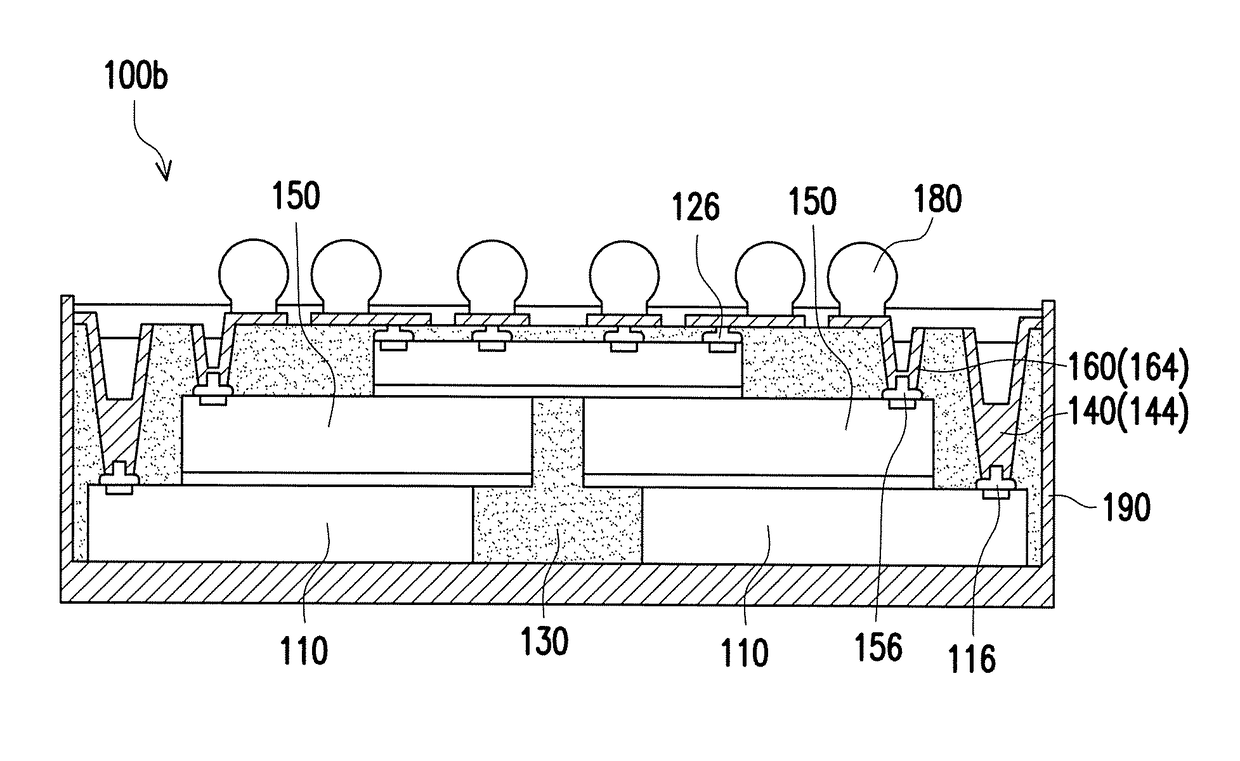
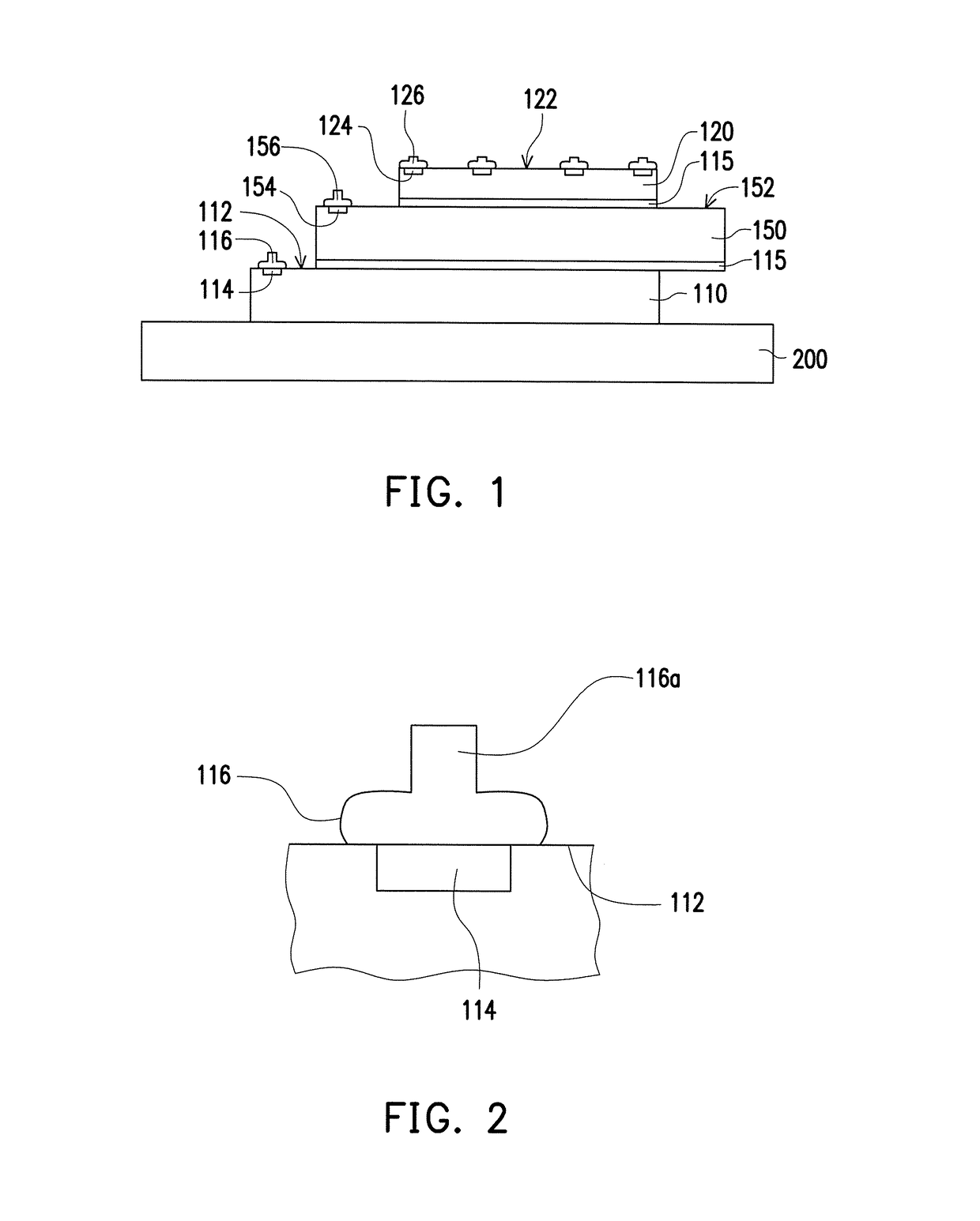
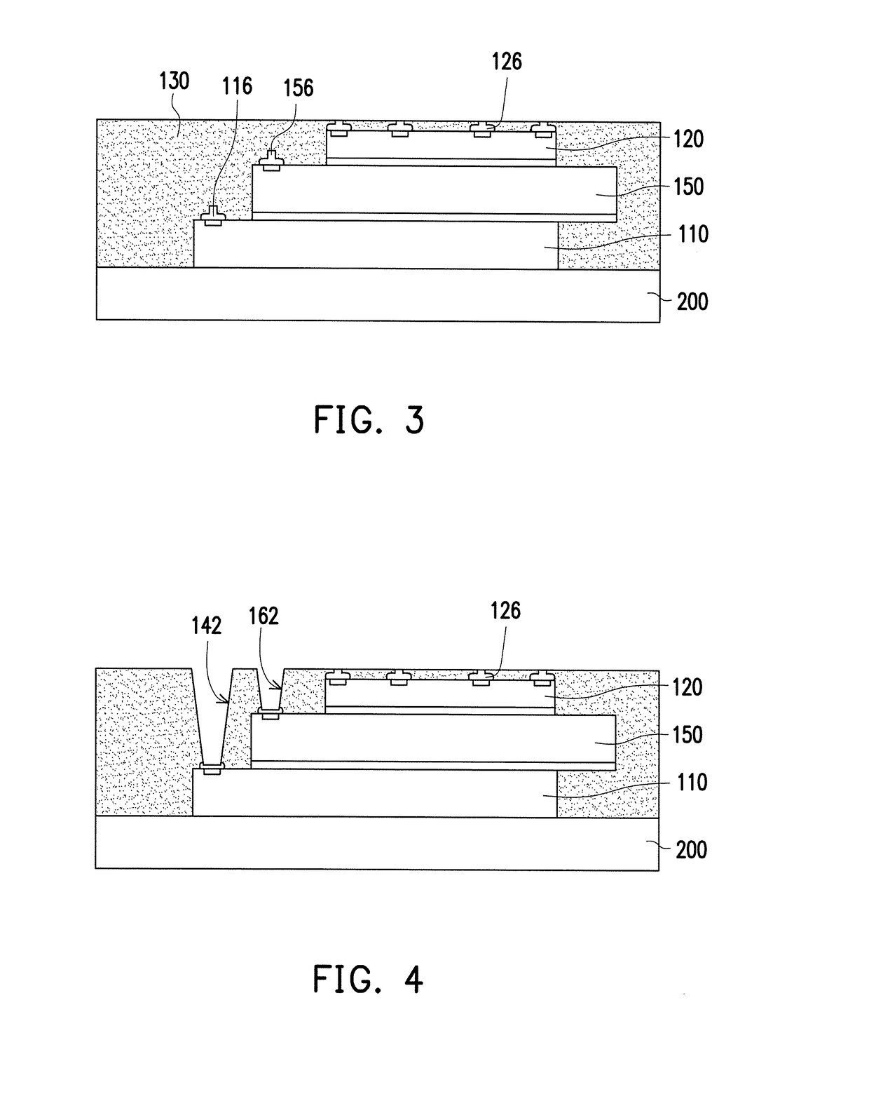
[0014]FIG. 1 to FIG. 8 illustrate cross-sectional views of a manufacturing process of a stacked chip package structure according to an embodiment of the invention. In the present embodiment, a manufacturing process of a stacked chip package structure may include the following steps. Referring to FIG. 1 and FIG. 2, a first chip 110 may be disposed on a carrier 200. The first chip 110 has a first active surface 112 and a plurality of first pads 114 disposed on the first active surface 112. A second chip 120 may then be disposed on the first chip 110. The second chip 120 may be disposed on the first chip 110 without covering the first pads 114 and may have a second active surface 122 and a plurality of ...


PUM


Abstract

A stacked chip package structure includes a first chip, stud bumps, a second chip, pillar bumps, an encapsulant and conductive vias. The first stud bumps are respectively disposed on a plurality of first pads of the first chip, wherein each first stud bump includes a rough surface, and the rough surface of each first stud bump is rougher than a top surface of each first pad. The second chip is disposed on the first chip and exposes the first pads. The pillar bumps are respectively disposed on a plurality of second pads of the second chips. The encapsulant encapsulates the first chip and the second chip and exposes a top surface of each second stud bump. The first conductive vias penetrate the encapsulant and connect the first stud bumps. Each first conductive via covers the rough surface of each first stud bump.

Description

CROSS-REFERENCE TO RELATED APPLICATION[0001]The application claims the priority benefit of U.S. provisional application Ser. No. 62 / 316,843, filed on Apr. 1, 2016 and Taiwan application serial no. 105137133, filed on Nov. 14, 2016. The entirety of each of the above-mentioned patent application is hereby incorporated by reference herein and made a part of this specification.BACKGROUND OF THE INVENTIONField of the Invention[0002]The present invention generally relates to a chip package structure and a manufacturing method thereof. More particularly, the present invention relates to a stacked chip package structure and a manufacturing method thereof.Description of Related Art[0003]Recently, attention has paid to a semiconductor device called a “substrate with a built-in chip” in which a chip and the like are embed in a substrate made of resin and the like and a semiconductor device in which an insulating layer and a wiring layer are formed on the chip. In semiconductor devices such as ...

Claims


Application Information

Patent Timeline
IPC IPC(8): H01L25/065H01L23/31H01L21/768H01L25/00H01L21/56H01L23/00H01L23/552
CPCH01L25/0652H01L2224/1134H01L23/3171H01L23/3128H01L23/552H01L24/09H01L25/50H01L24/11H01L24/03H01L21/568H01L21/76879H01L2225/06562H01L2225/06568H01L2225/06548H01L2224/0401H01L24/14H01L2224/83005H01L2224/24146H01L23/5389H01L24/19H01L24/24H01L24/32H01L24/82H01L2224/04105H01L2224/12105H01L2224/24145H01L2224/32145H01L2224/73267H01L2224/82005H01L2224/82039H01L2224/92244H01L2924/14H01L2924/1438H01L2924/3025H01L23/49816H01L2225/06527H01L25/0657
Inventor FANG, LI-CHIHLIN, JI-CHENGCHU, CHE-MINLIN, CHUN-TEHUANG, CHIEN-WEN
Owner POWERTECH TECHNOLOGY
Why Eureka
Try Eureka