Light weight housing for internal component and method of making

a technology of internal components and housings, applied in the direction of machines/engines, chemical vapor deposition coatings, metallic material coating processes, etc., can solve the problems of time to manufacture, cost of other desirable factors such as component weight, and cost to manufactur

Active Publication Date: 2017-10-12
RTX CORP
View PDF0 Cites 7 Cited by
  • Summary
  • Abstract
  • Description
  • Claims
  • Application Information

AI Technical Summary

Benefits of technology

[0014]In addition to one or more of the features described above, or as an alternative to any of the foregoing embodiments, further including the step of: heat treating the metallic foam core after the external metallic shell has been applied to the exterior surface of the metallic foam core.
[0015]In addition to one or more of the features described above, or as an alternative to any of the foregoing embodiments, further including the step of: forming additional features in the metallic foam core after the external metallic shell has been applied to the exterior surface of the metallic foam core.
[0016]In addition to one or more of the features described above, or as an alternative to any of the foregoing embodiments, wherein the additional features are formed by a drilling process.
[0017]In addition to one or more of the features described above, or as an alternative to any of the foregoing embodiments, wherein a supplemental application of the external metallic outer shell is applied to the metallic foam core after the drilling process.
[0018]In addition to one or more of the features described above, or as an alternative to any of the foregoing embodiments, wherein a thickness of the external metallic outer shell varies in order to provide localized structural rigidity to the component.
[0019]In addition to one or more of the features described above, or as an alternative to any of the foregoing embodiments, wherein the pre-machined component is a conduit.

Problems solved by technology

However, while a component may meet certain performance criteria it may be at the cost of other desirable factors such as component weight, time to manufacture and cost to manufacture.
However, and in this process, the monolithic nature of the raw input material means that the final part weight is driven by the final volume of the part and density of material used.

Method used


Image

  • Light weight housing for internal component and method of making
  • Light weight housing for internal component and method of making
  • Light weight housing for internal component and method of making

Examples


Embodiment Construction

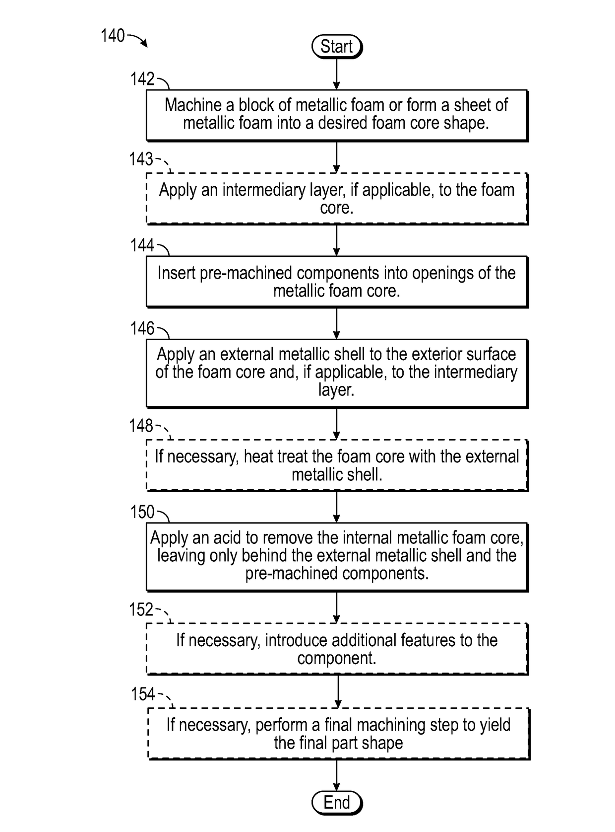
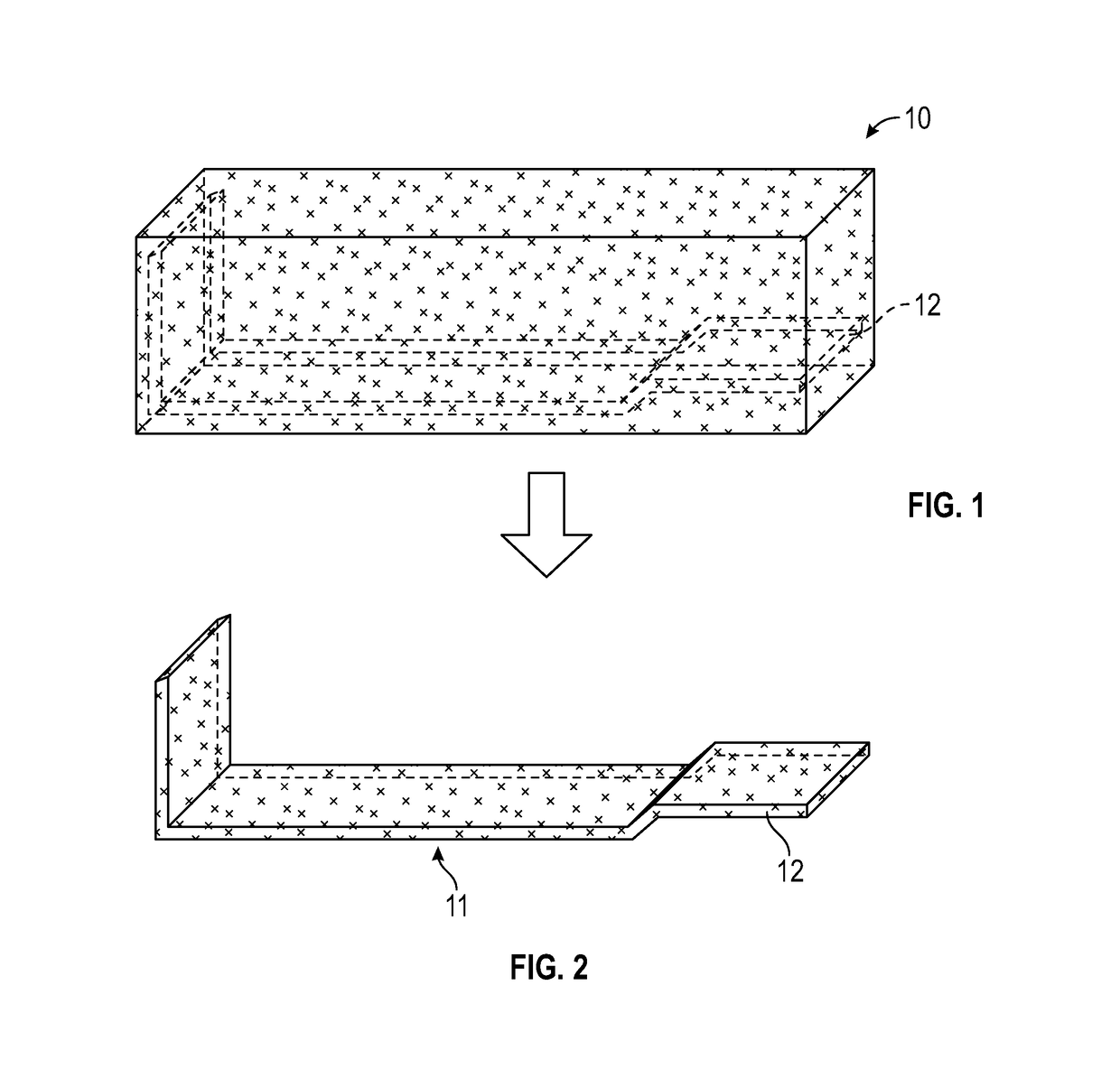
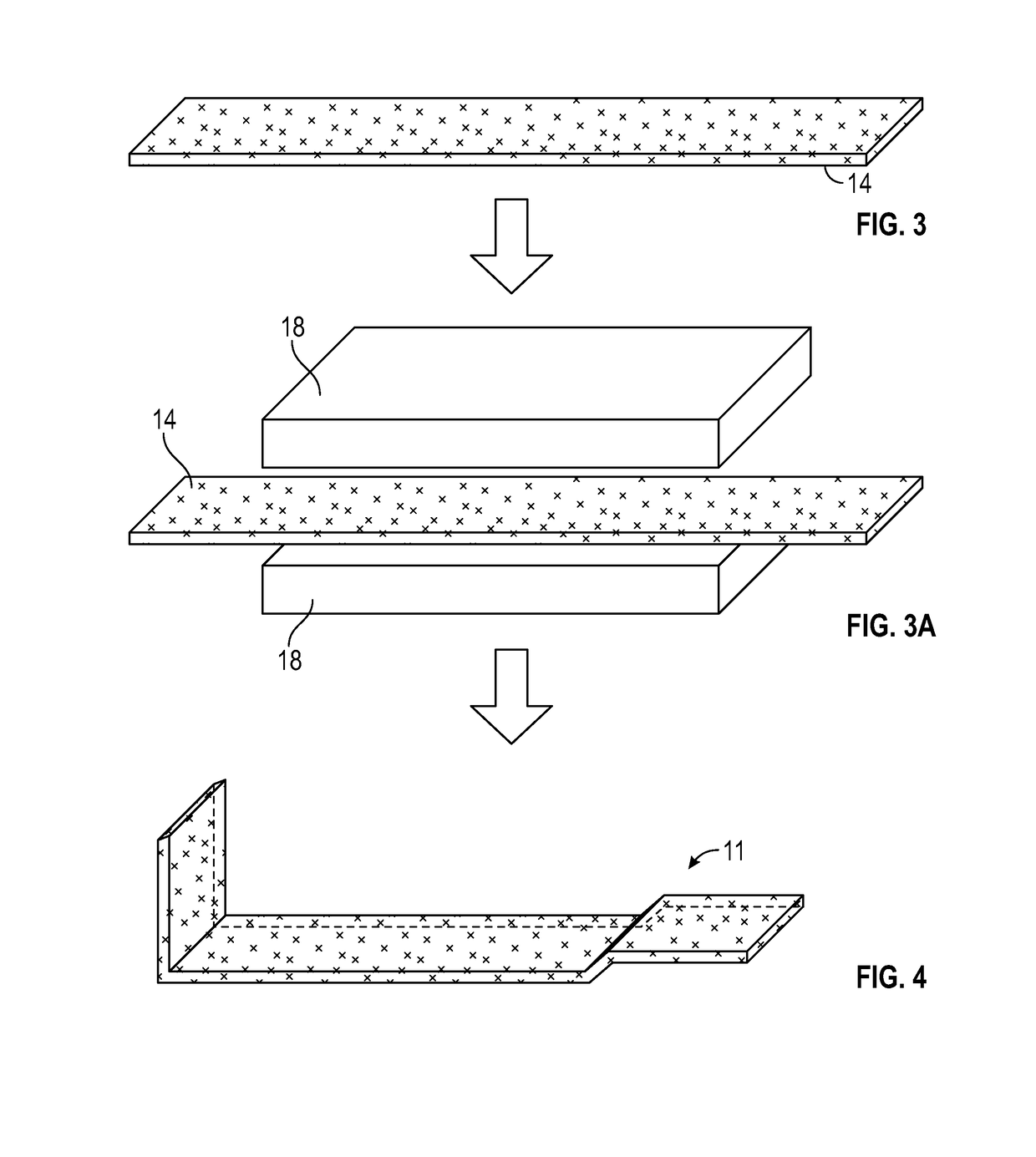
[0040]Various embodiments of the present disclosure are related to methods of making low cost, light weight components and components formed by the aforementioned methods. In particular, the present application is directed to a component having an internal foam core, which in one embodiment may be a metallic foam core or alternatively a non-metallic foam core such as a ceramic foam core or any other non-metallic foam core and an external metallic shell surrounding the metallic or non-metallic foam core and methods for making such a component.

[0041]The present disclosure is directed to a method of making a component using a combination of subtractive and additive manufacturing processes. In general, the method starts with a metallic foam core using alloy and foam density that is compatible with a specific design application. As mentioned above and in alternative embodiments, the foam core may be non-metallic. The metallic foam core is then machined or formed to a shaped pre-form for ...


PUM

PropertyMeasurementUnit
porosityaaaaaaaaaa
thicknessaaaaaaaaaa
thicknessaaaaaaaaaa

Abstract

A method of making a light weight component is provided. The method including the steps of: forming a metallic foam core into a desired configuration; inserting a pre-machined component into an opening in the metallic foam core; applying an external metallic shell to an exterior surface of the metallic foam core after it has been formed into the desired configuration and after the pre-machined component has been inserted into the metallic foam core; introducing an acid into an internal cavity defined by the external metallic shell; dissolving the metallic foam core; and removing the dissolved metallic foam core from the internal cavity, wherein the component and the external metallic shell are resistant to the acid.

Description

BACKGROUND[0001]This disclosure relates generally to methods of making low cost, light weight components and components formed by the aforementioned methods. In particular, the present application is directed to a component formed from a composite of metallic foam and an external metallic shell. In addition, various embodiments of the present disclosure are also directed to methods for making such a component.[0002]Commercially suitable components need to meet specific performance criteria. However, while a component may meet certain performance criteria it may be at the cost of other desirable factors such as component weight, time to manufacture and cost to manufacture. For example, subtractive manufacturing or machining oversized blocks, materials or forgings until a desired final part shape is achieved may be one process. However, and in this process, the monolithic nature of the raw input material means that the final part weight is driven by the final volume of the part and de...

Claims


Application Information

Patent Timeline
Patent Type & Authority Applications(United States)
IPC IPC(8): B21J5/00B23H1/08B23K26/40B23K26/362C25D3/12C25D5/40C25D5/48C25D7/04C23C14/16C23C14/02C23C14/22C23C4/08C23C4/129C23C4/134B23P15/02C23C24/04C23C16/44B23H9/00
CPCC23C14/16C23C16/44C23C14/221C23C4/08C23C4/129B21J5/002B23H9/00B23H1/08B23K26/40B23K26/362C25D3/12C25D5/40C25D5/48C25D7/04C23C4/134B23P15/02C23C24/04C23C14/028B22F7/002B32B5/18B32B5/20B32B15/01C22C1/08B32B2305/022F01D25/005F05D2300/612C23F1/04B22F2998/00B22F2998/10B22F2999/00B23K2103/02B23K2103/08B23K26/361Y02P10/25B22F3/1103B22F2003/244B22F2003/247B22F3/24B22F2003/242B22F3/115C22C23/00B22F10/66B22F10/25B22F10/62C22C1/083
Inventor ROBERGE, GARY D.
Owner RTX CORP
Why Eureka
Try Eureka