
Robot with daisy-chainable robot arm

Active Publication Date: 2017-10-12
FANUC LTD
View PDF1 Cites 2 Cited by
  • Summary
  • Abstract
  • Description
  • Claims
  • Application Information

AI Technical Summary

Benefits of technology

The patent aims to create a low-cost robot that has a reduced number of power line cables and makes it easy to rearrange the robot arm.

Problems solved by technology

As a result, the total wiring length of the power line cables is so long that twisting or interference of the wiring is a factor that restricts the operation of the robot.
However, with such a configuration, an increase in number of robot arms results in an increase in number of motors, the wiring number of power line cables connecting the motor drive units and the motors is increased.
As a result, the total wiring length of the power line cables is so long that twisting or interference of the wiring is a factor that restricts the operation of the robot.
In particular, in the case of an articulated robot that has robot arms each of which is provided with an alternating current motor are connected, the wiring number of power line cables is enormous and wiring patterns have significant limitations.
When the number of wires in power line cables and signal line cables is large, rearrangement work of a robot is not easy.
In short, the number of wires in a cable is increased even with the invention described in Japanese Patent No. 3534641, resulting in a redundant system and higher cost.

Method used


Image

  • Robot with daisy-chainable robot arm
  • Robot with daisy-chainable robot arm
  • Robot with daisy-chainable robot arm

Examples


Embodiment Construction

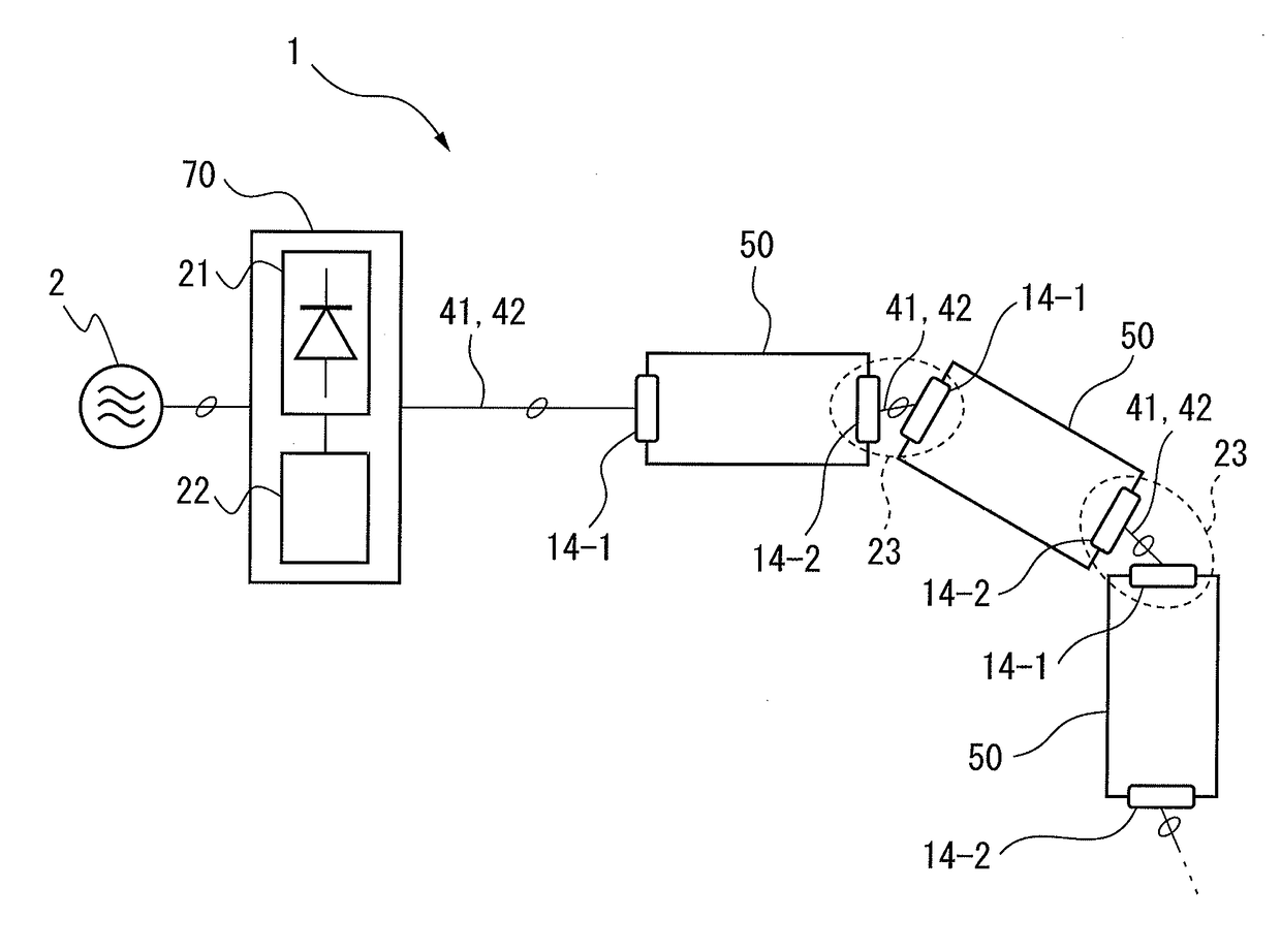
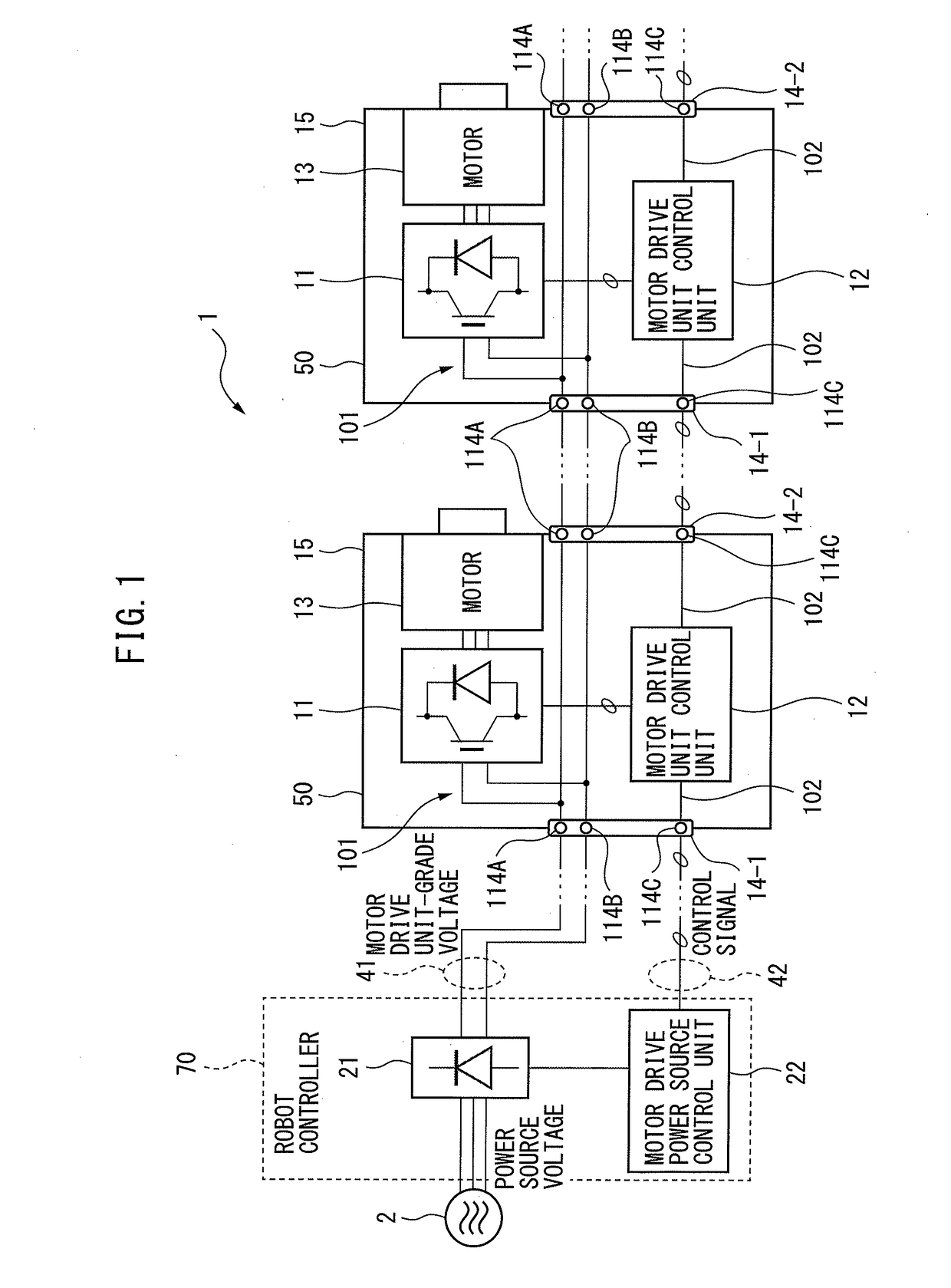
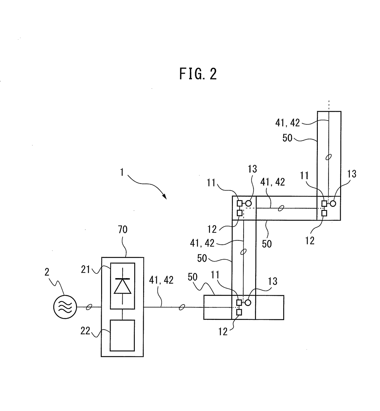
[0024]Next, embodiments of the present disclosure are described with reference to the drawings. In the following drawings, like members are designated with like reference numerals. For the sake of easy understanding, the scales of the drawings are properly changed. In addition, forms illustrated in the drawings are examples for carrying out the present disclosure, and the present disclosure is not limited to the illustrated forms.

[0025]FIGS. 1 and 2 are diagrams illustrating a robot according to one embodiment.

[0026]A robot 1 according to the one embodiment includes a motor drive power source 21, a motor drive unit control unit 12, an alternating current motor (hereinafter simply referred to as the “motor”) 13, a robot arm 50, and a robot controller 70.

[0027]The motor drive unit 11 converts a motor drive unit-grade voltage, which is a direct current voltage output from the motor drive power source 21 to be described below, to a motor drive voltage, which is a three-phase alternating...


PUM


Abstract

A robot includes a motor drive power source for converting a voltage supplied from a power source to a motor drive unit-grade voltage and outputting it, a motor drive unit for converting a motor drive unit-grade voltage output from the motor drive power source to a motor drive voltage and outputting it, a motor driven to be rotated by a motor drive voltage output by the motor drive unit, a robot arm on which the motor drive unit and the motor are arranged, and a robot controller which is provided independently of the robot arm and on which the motor drive power source is arranged.

Description

BACKGROUND OF THE INVENTION1. Field of the Invention[0001]The present invention relates to a robot including a robot arm capable of daisy-chaining.2. Description of the Related Art[0002]Generally, a robot uses an alternating current voltage as a voltage for driving a motor provided on a robot arm. Therefore, the robot includes a motor drive power source and a motor drive unit as a system for driving a motor. The motor drive power source is a converter that rectifies a three-phase alternating current voltage supplied from the alternating current power source side and outputs a direct current voltage to a DC link (direct current link), and the motor drive unit is an inverter that is connected to the DC link, which is the direct current side of the motor drive power source, converts a direct current voltage on the DC link side to an alternating current voltage through switching operation of an internal switching element, and supplies the alternating current voltage to an alternating cu...

Claims


Application Information

Patent Timeline
IPC IPC(8): B25J9/12
CPCY10S901/23B25J9/12H02P5/74B25J9/1602G05B2219/33226G05B2219/39001G05B19/00
Inventor SAITOU, SOUSHIKAGAWA, TSUTOMUINABA, KIICHI
Owner FANUC LTD
Learn More