Bolt On Seal Ring

Inactive Publication Date: 2017-10-19
SIEMENS ENERGY INC
View PDF8 Cites 1 Cited by
  • Summary
  • Abstract
  • Description
  • Claims
  • Application Information

AI Technical Summary

Benefits of technology

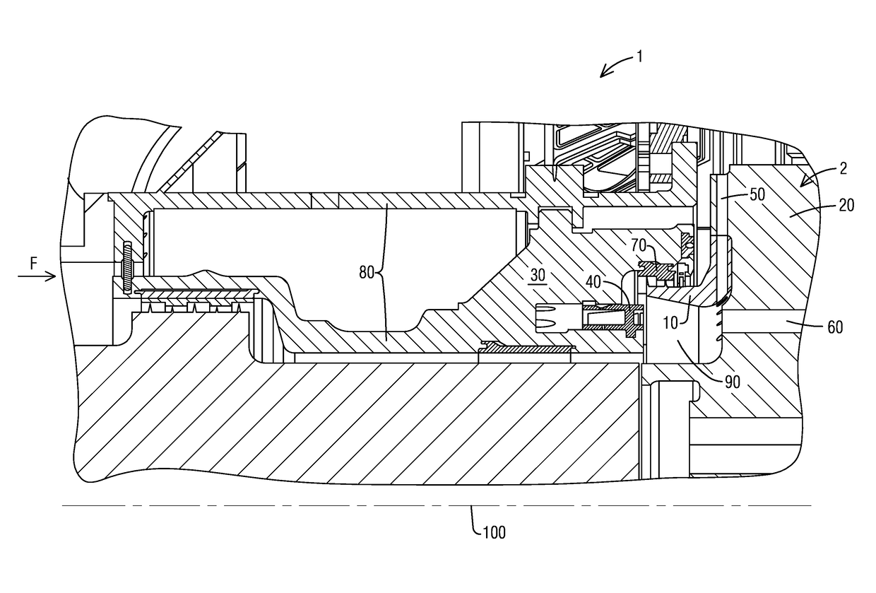
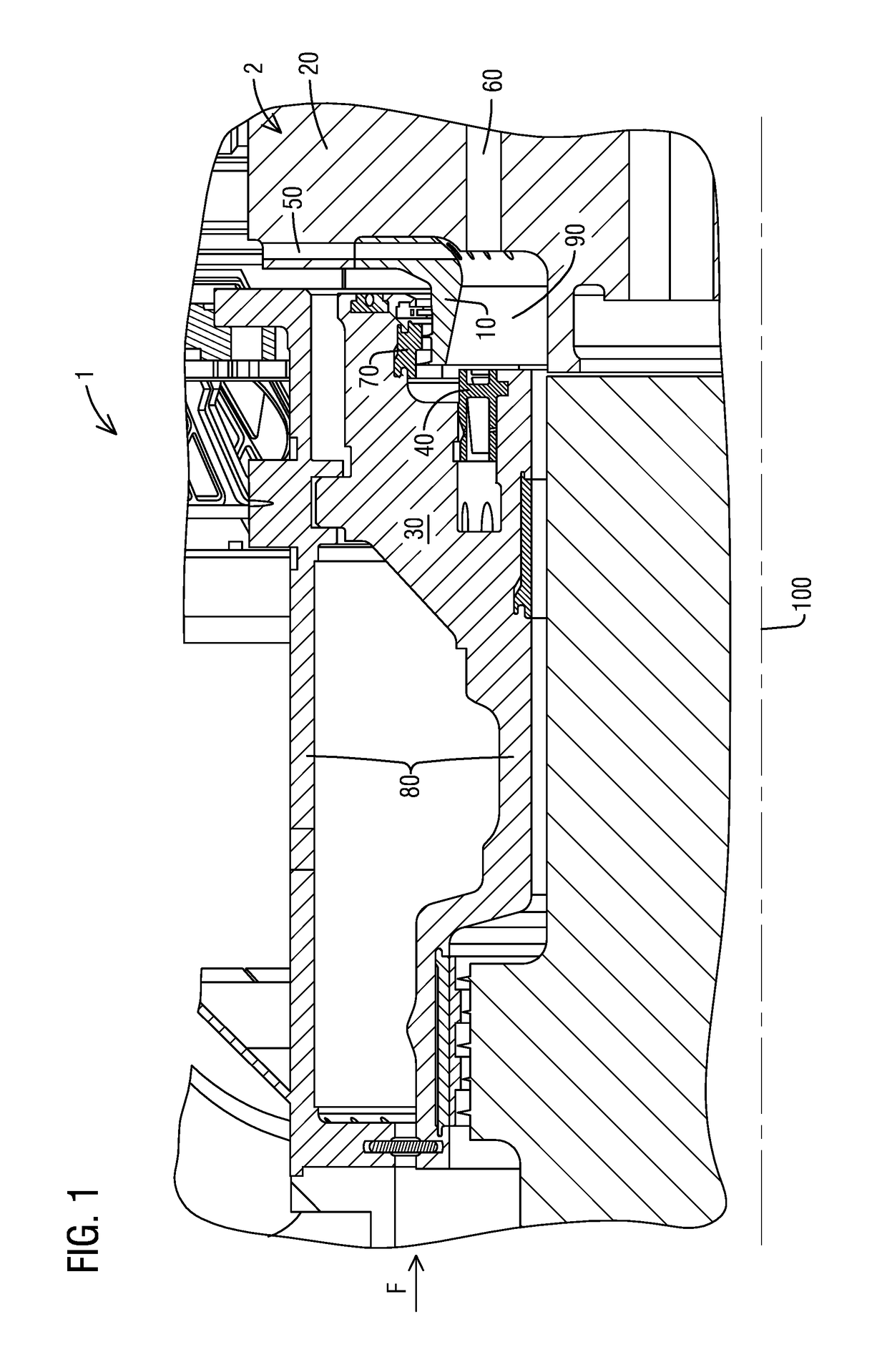
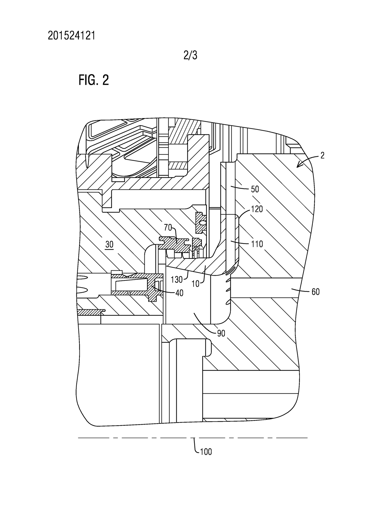
The present disclosure relates to a device, system, and method for routing cooling air to a turbine blade. The device includes an L-shaped seal ring with cooling holes that route cooling air from a swirler device to the turbine blade. The system also includes a swirler device that swirl the cooling air and an L-shaped seal ring that routes the cooling air to the turbine blade. The method involves swirling the cooling air and routing it to the turbine blade through a radial hole in the L-shaped seal ring. These improvements can enhance the flow of cooling air to the turbine blade, thereby improving the cooling efficiency and performance of the gas turbine.

Problems solved by technology

During operation of the gas turbine, turbine blades are exposed to extremely high temperatures.
This process incurs undesirable aerodynamic losses as the work of the rotor associated with bringing the air up to rotational speed is high.

Method used


Image

  • Bolt On Seal Ring
  • Bolt On Seal Ring
  • Bolt On Seal Ring

Examples


Embodiment Construction

[0011]To facilitate an understanding of embodiments, principles, and features of the present disclosure, they are explained hereinafter with reference to implementation in illustrative embodiments. Embodiments of the present disclosure, however, are not limited to use in the described systems or methods.

[0012]The components and materials described hereinafter as making up the various embodiments are intended to be illustrative and not restrictive. Many suitable components and materials that would perform the same or a similar function as the materials described herein are intended to be embraced within the scope of embodiments of the present disclosure.

[0013]The pre-swirler device, as described above, would physically replace the air separator in existing gas turbines. In order to integrate the pre-swirler into existing gas turbines, an additional device may be needed to replace the functionality of the air separator; that is to separate the cooling air into the two paths, one path ...


PUM


Abstract

A device to route cooling air to a turbine blade is provided. The device includes a seal ring having an L-shaped cross section configured to abut a turbine disc. The seal ring includes a radial portion extending radially with respect to a rotor and an axial portion extending axially with respect to the rotor. The seal ring also includes a plurality of radial cooling holes disposed within the radial portion of the seal ring and arranged circumferentially around the seal ring. The plurality of cooling holes route cooling air from a device configured to impart tangential momentum to the cooling air to a turbine blade in order to cool the turbine blade. A system and a method to improve a flow of rotor cooling air to a turbine blade are also provided.

Description

BACKGROUND1. Field[0001]The present application relates to gas turbines, and more particularly to a device to route cooling air to a turbine blade. A system to improve a flow of rotor cooling air and a method to improve a flow of rotor cooling air to a turbine blade are also provided.2. Description of the Related Art[0002]During operation of the gas turbine, turbine blades are exposed to extremely high temperatures. Various methods are employed for their cooling, including routing rotor cooling air to the turbine blades. Traditionally, an air separator is used to separate the air into two paths, one leading into the row one turbine disc, also referred to as the turbine disc one, for cooling of the row one blade platform and the other path leading to the rotor for cooling of the rotor discs and turbine blades. After the air separator routes the air to the rotor, the air is then brought up to the rotational speed of the rotor. This process incurs undesirable aerodynamic losses as the ...

Claims


Application Information

Patent Timeline
IPC IPC(8): F01D5/08F01D11/00
CPCF01D5/085F01D11/00F05D2220/32F05D2260/20F05D2260/14F01D11/001
Inventor PATEL, CHIRAG B.SKARBOWSKI, MICHAELLIGHT, KEVIN M.CURTIN, WILLIAM J.
Owner SIEMENS ENERGY INC
Why Eureka
Try Eureka