
Contaminant monitor system and method

a monitor system and contaminant technology, applied in water treatment parameter control, instruments, chemistry apparatus and processes, etc., can solve the problems of arsenic being toxic, access to clean water can often evade even those in the developed world, etc., and achieve the effect of convenient us

Active Publication Date: 2017-10-19
ARIANA SCHANZER
View PDF6 Cites 14 Cited by
  • Summary
  • Abstract
  • Description
  • Claims
  • Application Information

AI Technical Summary

Benefits of technology

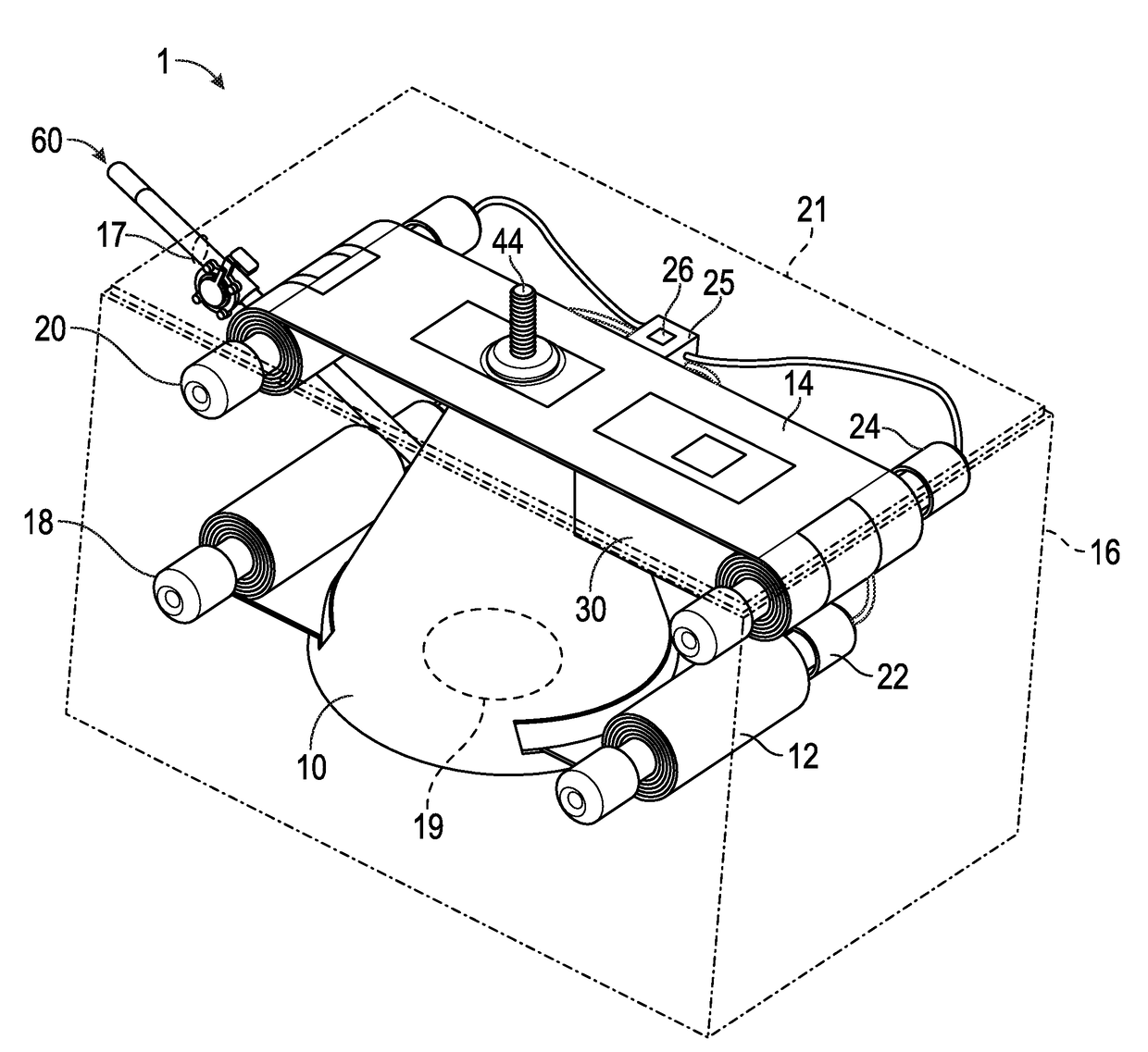
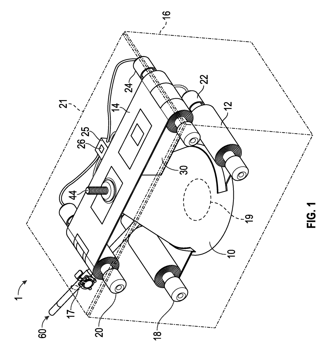
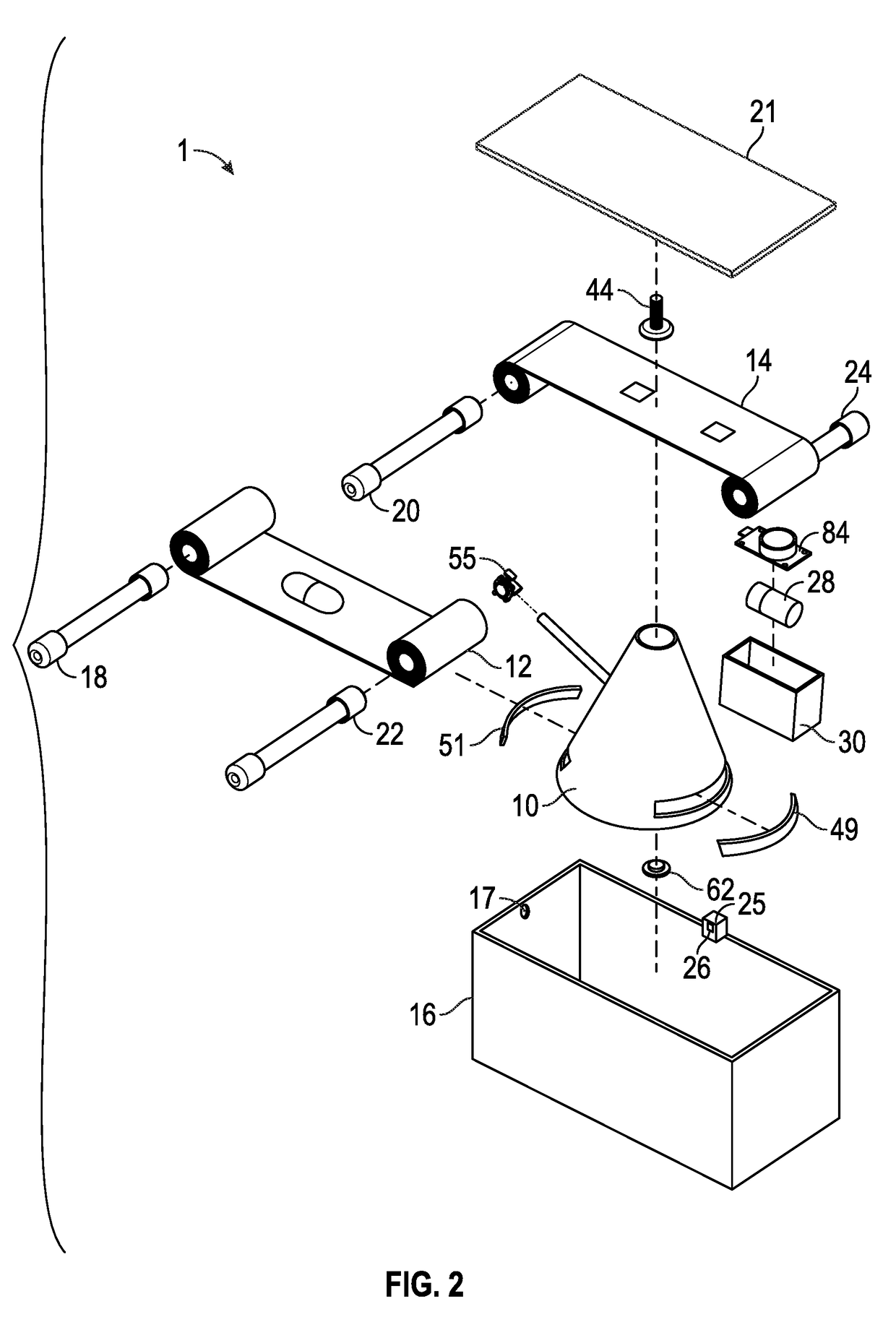
This patent describes a new way to deliver reagents for monitoring and quantifying contaminants. With this method, users don't have to replace the reagents for several months at a time. The system is designed to be easy to use, accurate, efficient, and effective over a long period of time. Overall, this technology provides a better solution for monitoring contaminants and their levels in various settings.

Problems solved by technology

Access to clean water can often evade even those in the developed world.
For example, arsenic is a toxic substance due to its threat to human health and the high likelihood of being exposed.

Method used


Image

  • Contaminant monitor system and method
  • Contaminant monitor system and method
  • Contaminant monitor system and method

Examples


second embodiment

[0038]With reference to FIG. 3B, a reaction chamber 10′ is illustrated for a contaminant sensor system 1′ (FIG. 8). The reaction chamber 10′ and other components of the system 1′ are substantially similar to the counterparts in the system 1, except as specifically noted and / or shown, or as would be inherent. In this embodiment, the reaction chamber 10′ is frusto-pyramidal shaped and the top surface 40′ is closed or sealed off. Near the top surface 40′ is situated a second set of opposed side apertures 68′, 69′. Like the lower opposed side apertures 46′, 47′, each aperture 68′, 69′ may be identical to each other and are sized and shaped to allow a second reagent sheet 14′ therethrough (FIG. 8). The opposed apertures 68′, 69′ are near enough to the top surface 40 such that when a predetermined amount of fluid sample is introduced into the reaction chamber 10′, the second reagent sheet 14′ is not situated too close to the first reagent sheet 12′. Each of the second set of opposed apert...

third embodiment

[0039]With reference to FIG. 3C, a reaction chamber 10″ is illustrated for a contaminant sensor system 1″ (FIG. 9). The reaction chamber 10″ and other components of the system 1″ are substantially similar to the counterparts in the system 1, except as specifically noted and / or shown, or as would be inherent. In this embodiment, the reaction chamber 10″ is frusto-hexagonally shaped and a top surface 40″ is closed or sealed off. In this embodiment 1″, there is only the first reagent sheet 12″ and a second reagent sheet is not necessary, as will be further discussed below.

fourth embodiment

[0040]With reference to FIG. 3D, the reaction chamber 10′″ is illustrated for a contaminant sensor system (not shown). The reaction chamber 10′″ and other components of the system substantially similar to the counterparts in the system 1, except as specifically noted and / or shown, or as would be inherent. The reaction chamber has an exterior of two opposed frusto-cones stacked base to base creating a frusto-diamond-like cross section. In this embodiment, it is envisioned that the bottom may have a bottom aperture as in the top aperture 42″, such that first reagent sheet seals a bottom aperture or it may be closed off as illustrated, where a first reagent sheet may pass through the downward directed frusto-cone near a bottom 48′″ thereof and the second reagent sheet either passes through the upward directed frusto-cone or seals a top aperture 42′″ as illustrated.

[0041]Referring now to FIG. 4, the first reagent sheet 12 is illustrated. The reagent sheet 12 may be made from at least on...


PUM

PropertyMeasurementUnit
densityaaaaaaaaaa
volumeaaaaaaaaaa
volumeaaaaaaaaaa

Abstract

Embodiments of the present invention are directed to methods, systems, and software for assessing contaminant quantities in a fluid. Fluid enters a reaction chamber. A controller then signals two different sheets with different reagents to move into the reaction chamber. One sheet contains reagents to form a contaminant byproduct or gas, while the other sheet is saturated with reagent that will have a photometric effect upon reacting with the contaminant byproduct or gas. After the photometric effect has occurred, the controller moves the reacted portion of the other reagent sheet into alignment with a photometric sensor. This photometric effect is calculated to contaminant concentration. The concentration is recorded and the data is transmitted to memory. The fluid sample in the chamber is drained and the remaining solid waste is collected onto the first reagent sheet. Both sheets are individually collected into separate controllable collectors.

Description

CROSS REFERENCE TO RELATED APPLICATIONS[0001]This application claims priority to U.S. Provisional Patent Application Ser. No. 62 / 324,863, filed Apr. 19, 2016, the disclosure of which is incorporated herein by reference in its entirety.FIELD[0002]Embodiments of the present disclosure are directed to methods and apparatus for assessing and quantifying contaminates in a fluid.BACKGROUND[0003]Access to clean water can often evade even those in the developed world. More than 783 million people around the world suffer because of contamination of their water supply. For example, arsenic is a toxic substance due to its threat to human health and the high likelihood of being exposed. Over 140 million people have arsenic contamination in their water supplies. Prolonged arsenic poisoning has been linked to various cancers, reproductive disorders, dermatological problems and more. Technological advances can play a vital role in addressing this and other water contamination issues.[0004]By detec...

Claims


Application Information

Patent Timeline
Patent Type & Authority Applications(United States)
IPC IPC(8): G01N21/27G01N21/25G01N1/10G01N21/94
CPCG01N21/272G01N1/10C02F2209/003G01N21/255C02F2209/001G01N21/94G01N1/2035G01N21/77G01N21/78G01N21/8483G01N33/1813G01N2001/205G01N2021/7759G01N2021/7773G01N2021/7786
Inventor SCHANZER, ARIANAGOLDBERGER, MICHALERAJENDRAN, AARDRAWEISEL, ADAM
Owner ARIANA SCHANZER
Learn More