
Grinding system for grinding a material to be ground, and method for grinding a material to be ground

a technology of grinding system and grinding material, which is applied in the direction of grain treatment, etc., can solve the problems of increased wear inability to achieve adequate comminution of the material for grinding in the grinding apparatus, and so as to prevent overloading of the grinding apparatus and facilitate efficient comminution of the material for grinding

Inactive Publication Date: 2017-10-26
THYSSENKRUPP IND SOLUTIONS AG +1
View PDF5 Cites 2 Cited by
  • Summary
  • Abstract
  • Description
  • Claims
  • Application Information

AI Technical Summary

Benefits of technology

The present invention provides a grinding installation that overcomes disadvantages and prevents overloading of the grinding apparatus. It achieves efficient comminution of material for grinding by using an open-loop / closed-loop control device and a dosing device. The dosing device limits the stream of material for grinding to the grinding apparatus, avoiding excessive flow rates and ensuring efficient operation. A measurement device is used to register process fluctuations and adjust the feed rate of fresh material fed into the grinding installation. A buffer store is used to store excess grit and allow for targeted buffering of a partial stream. Overall, the grinding installation achieves improved grinding efficiency and prevents damage to the grinding apparatus.

Problems solved by technology

Such process fluctuations lead to overloading of the grinding apparatus, wherein adequate comminution of the material for grinding is no longer achieved in the grinding apparatus.
This leads firstly to increased wear of the grinding apparatus and secondly to a situation in which the material for grinding that has not been adequately comminuted is supplied to the grinding apparatus again, and the grinding process is lengthened considerably.

Method used


Image

  • Grinding system for grinding a material to be ground, and method for grinding a material to be ground
  • Grinding system for grinding a material to be ground, and method for grinding a material to be ground
  • Grinding system for grinding a material to be ground, and method for grinding a material to be ground

Examples


Embodiment Construction

[0030]The invention will be discussed in more detail below on the basis of multiple exemplary embodiments with reference to the appended figures. Here, statements such as “above” and “below” or “left” and “right” serve for better explanation of the schematic illustration of the exemplary embodiments of the invention shown in the figures, without the invention being restricted to the exemplary embodiments shown or to a particular installation position.

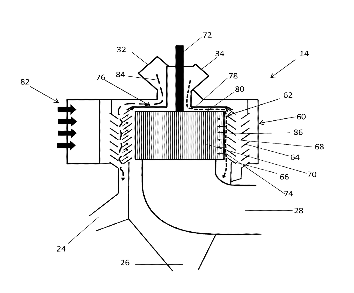
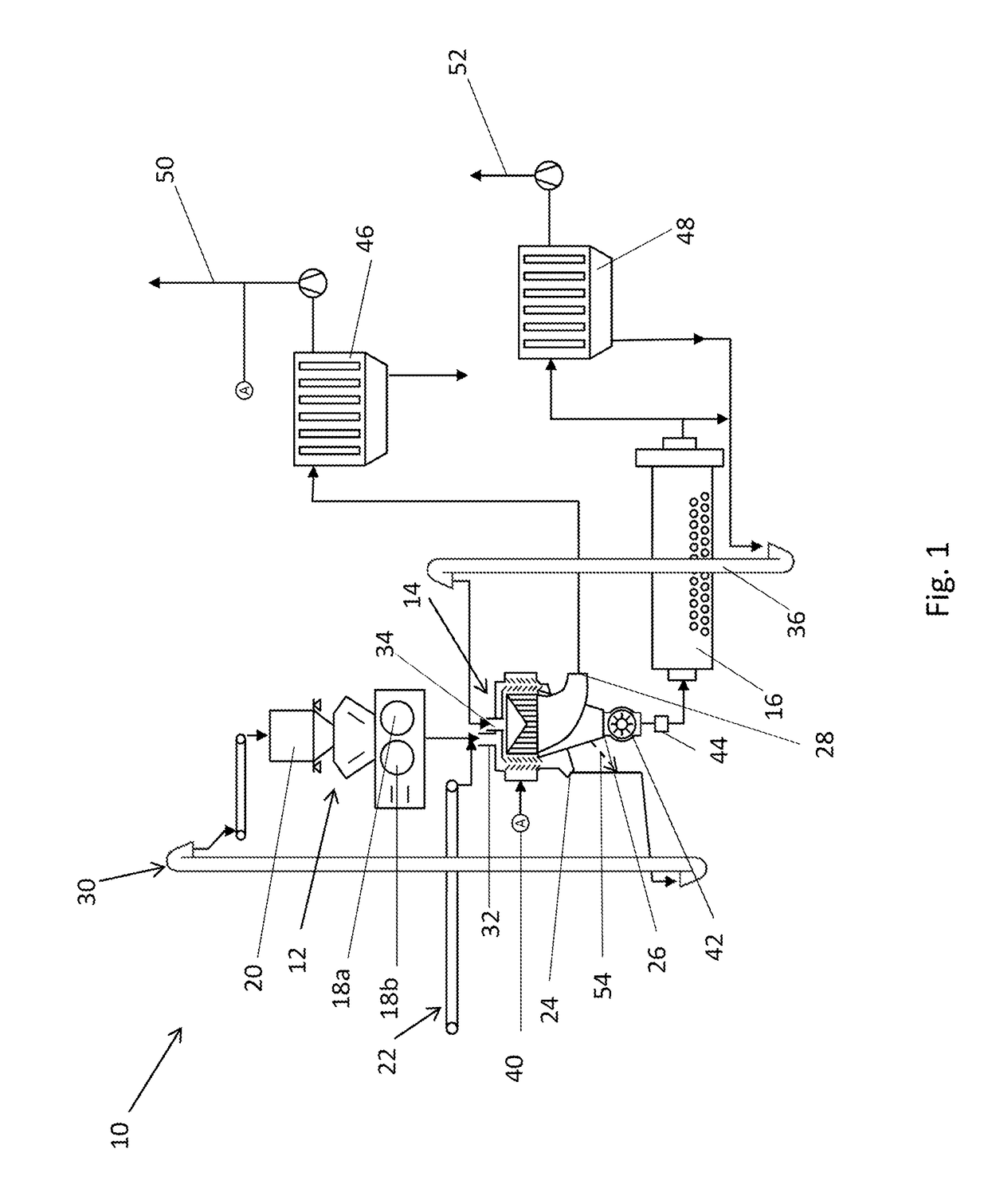
[0031]FIG. 1 shows a schematic illustration of a grinding installation comprising a classifying device and comprising two grinding apparatuses according to an exemplary embodiment.

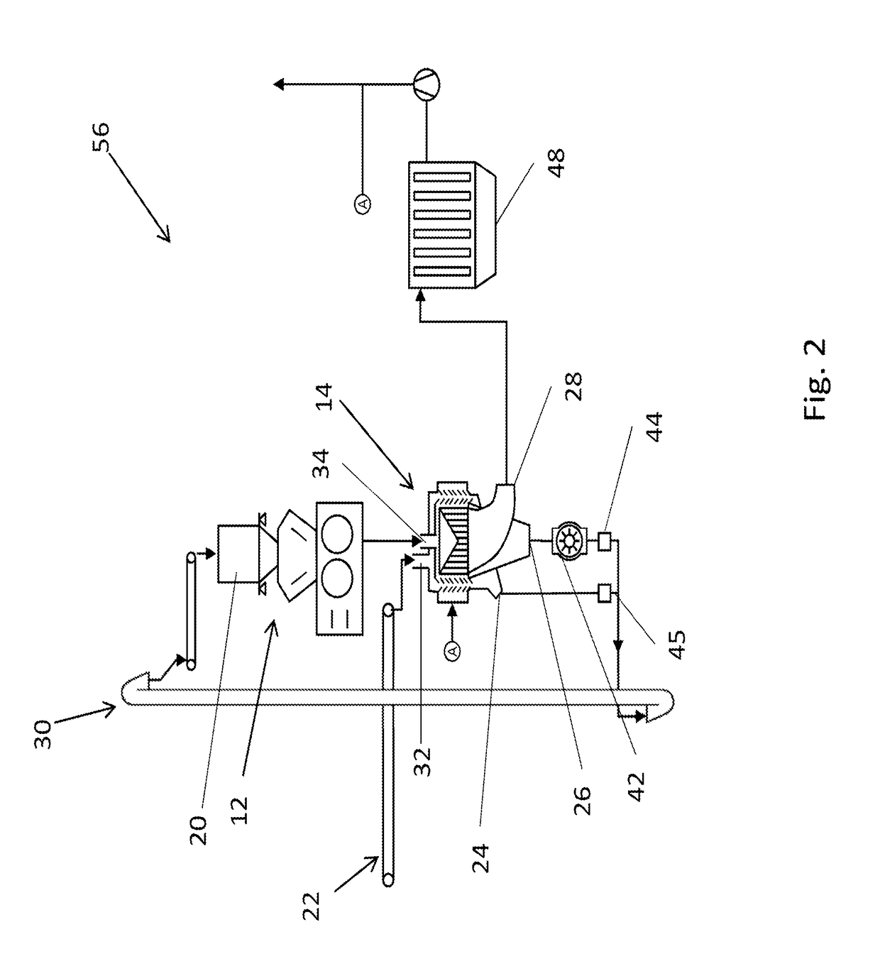
[0032]FIG. 2 shows a schematic illustration of a grinding installation comprising a classifying device and comprising a roller press according to a further exemplary embodiment.

[0033]FIG. 3 shows a schematic illustration of a grinding installation comprising a classifying device and comprising a ball mill according to an exemplary embodiment.

[0034]FIG. 4 shows...


PUM


Abstract

A grinding installation for comminuting material may include a grinding apparatus and a classifying device that is connected to the grinding apparatus and classifies the material. The classifying device may include a static classifier and a dynamic classifier. The static classifier may be disposed so as to at least partially surround the dynamic classifier. The classifying device may comprise a coarse material outlet for discharging coarse material that comprises a coarse grain fraction, a grit outlet for discharging grit that comprises a medium grain fraction, and a finished material outlet for discharging finished material that comprises a fine grain fraction. The grinding installation may further include an open-loop / closed-loop control device for open-loop / closed-loop control of at least a part of a stream of material to the grinding apparatus. The present disclosure also concerns methods for comminuting material.

Description

[0001]The invention relates to a grinding installation for comminuting material for grinding, and to a method for comminuting material for grinding.PRIOR ART[0002]It is known for material for grinding, such as for example limestone, dolomite, ores, clinker, slag or fly ash to be comminuted in a grinding installation which comprises at least one grinding apparatus and one classifier.[0003]DE 102011055762 A1 has disclosed a grinding installation for comminuting material for grinding, which grinding installation comprises a classifying device with a static classifier and a dynamic classifier and with at least one grinding apparatus.[0004]The material for grinding is normally fed into the classifier or the grinding apparatus. In the classifier, the material for grinding is classified into a fine grain fraction and a coarse grain fraction, wherein the coarse grain fraction is fed to the grinding device for comminution. Following the comminution, the material for grinding is classified in...

Claims


Application Information

Patent Timeline
IPC IPC(8): B02C23/08B02C15/00B02C17/16B02C23/02
CPCB02C23/08B02C15/00B02C17/161B02C23/02B02C25/00B02C23/10B02C23/14
Inventor HAGEMEIER, OLAFWILCZEK, MICHAEL
Owner THYSSENKRUPP IND SOLUTIONS AG
Learn More