Turbine blade having an inner module and method for producing a turbine blade

Inactive Publication Date: 2017-10-26
SIEMENS AG
View PDF0 Cites 26 Cited by
  • Summary
  • Abstract
  • Description
  • Claims
  • Application Information

AI Technical Summary

Benefits of technology

[0035]It is advantageous if the outer side of the inner module is connected to the inner side of the casing by mechanical positive locking. This is made possible by the formation of the supporting profiles by means of selective laser melting and the casting mold of the casing with the corresponding positively locking structures, that is to say corresponding recesses.
[0036]It is furthermore advantageous

Problems solved by technology

In present embodiments of gas turbines, in the interests of effective cooling, disadvantages are also accepted with regard to costs, component service life, efficiency and power.
Conventional core production processes for turbine blades are limited with regard to core geometry complexity, core stability, geometry part resolution and with regard to other criteria.
The production process is also relatively expensive owing to the high reject rate.
In the case of rotor blades with cores from conventional microprocesses, the cooling air flow runs primarily in a radial direction, which limits optimum utilization of the cooling air potential, specifically from the aspect that, with increased local heat transfer, there is often a need for a general increase in the cooling air mass flow of the blades in order to be able to dissipate the heat from the component too.
In particular in the case of rotor blades but also in the case of guide blades of turbines, the problem often arises that stresses arising in the component as a result of thermal loading, on the one hand, and as a result of effective cooling, on the other hand, reduce service life, or the design is limited because, in the component, there are regions in which very hot regions,

Method used


Image

  • Turbine blade having an inner module and method for producing a turbine blade
  • Turbine blade having an inner module and method for producing a turbine blade
  • Turbine blade having an inner module and method for producing a turbine blade

Examples


Example

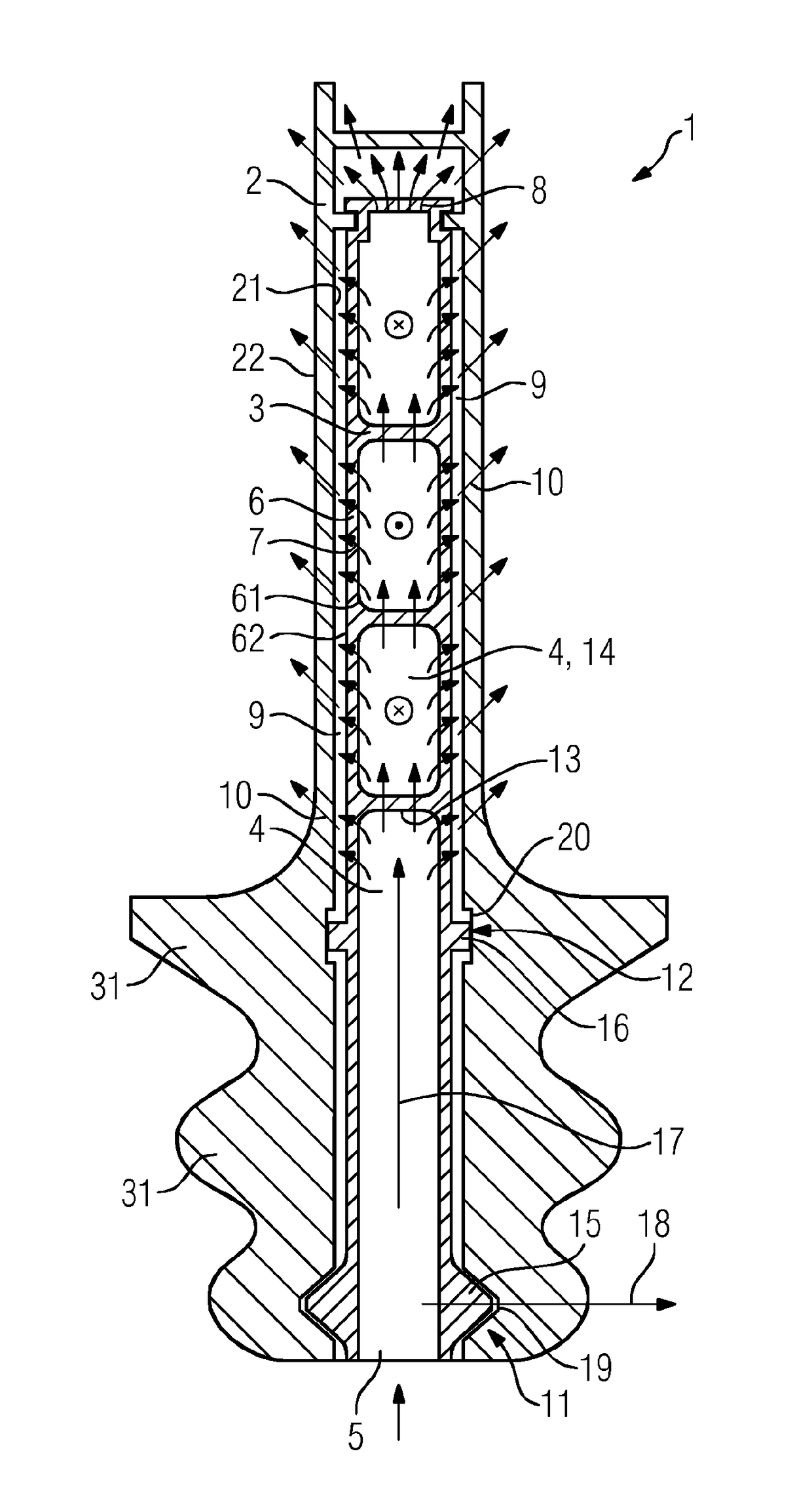
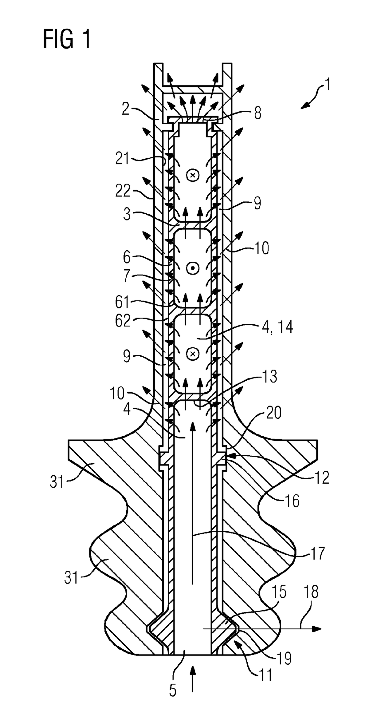
[0055]In the embodiment illustrated by way of example in FIG. 1, the turbine blade 1 comprises a casing 2 and an inner module 3. The inner module 3 is adapted substantially to the shape of the casing 2. The inner module 3 has an interior space 4 through which flow can pass in a longitudinal direction 17 of the inner module 3 and which has an inflow opening 5 and a wall 6 with a number of ducts 7, through which ducts flow can pass in a radial direction 18 and which ducts connect an inner side 61 to an outer side 62 of the wall 6 of the inner module 3. Furthermore, the illustrated inner module 3 has, in the distal region of the wall 6, a number of ducts 8 through which flow can pass in the longitudinal direction 17, which ducts are in this case arranged in addition to the ducts 7, through which flow can pass in the radial direction, in the lateral region of the wall 6.

[0056]Between the inner module 3 and casing 2 there is provided a peripheral intermediate space 9 which is delimited b...


PUM

PropertyMeasurementUnit
Angleaaaaaaaaaa

Abstract

A turbine blade having a casing and having an inner module, wherein a cooling medium can flow through the inner module both in a longitudinal direction and in a radial direction, and the inner module is attached to the casing by fixed bearings and floating bearings. A method for producing a turbine blade having an inner module and having a casing is produced by selective laser melting.

Description

CROSS REFERENCE TO RELATED APPLICATIONS[0001]This application is the US National Stage of International Application No. PCT / EP2015 / 073258 filed 8 Oct. 2015, and claims the benefit thereof. The International Application claims the benefit of German Application No. DE 102014220787.8 filed 14 Oct. 2014. All of the applications are incorporated by reference herein in their entirety.FIELD OF INVENTION[0002]The invention relates to a turbine blade having an inner module, and to a method for producing said turbine blade by means of selective laser melting.BACKGROUND OF INVENTION[0003]Gas turbines are used as power machines for various installations, for example in power plants, in jet engines and similar gas turbine components, in particular turbine guide and rotor blades, though ring segments or components from the region of the combustion chamber are also exposed to high thermal and mechanical loads during the operation thereof. For this reason, they are commonly cooled using compressor ...

Claims


Application Information

Patent Timeline
IPC IPC(8): F01D5/18B33Y80/00B23K26/342F01D5/28B33Y10/00B22D18/06B22F5/00B22C9/04B23K101/00
CPCF01D5/187F01D5/28B33Y10/00B33Y80/00B22C9/04B23K2201/001B22F5/007B23K26/342F05D2220/32F05D2230/31F05D2260/202B22D18/06B22F5/04F01D5/186F01D5/189F05D2260/30F05D2260/36F05D2260/201F05D2230/211F05D2230/22B22F10/00B22F10/28B22F3/24B22F2005/005B23K2101/001Y02P10/25Y02T50/60
Inventor MUNZER, JAN
Owner SIEMENS AG
Why Eureka
Try Eureka