MIMO radar device for the decoupled determination of an elevation angle and an azimuth angle of an object and method for operating a MIMO radar device

a radar device and mimo technology, applied in the direction of differential interacting antenna combinations, instruments, and using reradiation, can solve the problems of increasing computing effort and excessive distance to the preceding road user, and achieve the effect of more precise determination of elevation angle and the lik

Active Publication Date: 2017-10-26
ROBERT BOSCH GMBH
View PDF3 Cites 45 Cited by
  • Summary
  • Abstract
  • Description
  • Claims
  • Application Information

AI Technical Summary

Benefits of technology

[0025]According to one preferred refinement, each of the transmitting antennas is spaced apart from each other one of the transmitting antennas along the second coordinate direction either not at all or by the offset value. According to another preferred refinement, each of the receiving antennas is spaced apart from each other one of the receiving antennas along the second coordinate direction either not at all or by the offset value. In this way, the arrangement of the virtual phase centers in the virtual array is advantageous for the more precise determination of the elevation angle and the azimuth angle.
[0026]According to another preferred refinement, the phase center of a second transmitting antenna, which is situated between a first and a third transmitting antenna, is spaced apart by the offset value from the phase centers of the first and the third transmitting antennas along the second coordinate direction. According to another preferred refinement, the phase center of a second receiving antenna, which is arranged along the first coordinate direction between a first and a fourth receiving antenna, is spaced apart by the offset value from the phase centers of the first and the fourth receiving antennas along the second coordinate direction. According to another preferred refinement, the phase center of a third receiving antenna, which is situated between the second and fourth receiving antennas along the first coordinate direction, is spaced apart by the offset value from the phase centers of the first and the fourth transmitting antennas along the second coordinate direction. The arrangement of the virtual phase centers in the virtual array is advantageous for the more precise determination of the elevation angle and the azimuth angle due to these refinements.

Problems solved by technology

Such brake assistants may also initiate emergency braking if they recognize that the distance to the preceding road user becomes excessively small.
The computing effort thus increases greatly.
A particularly small overall size may result in this way.

Method used


Image

  • MIMO radar device for the decoupled determination of an elevation angle and an azimuth angle of an object and method for operating a MIMO radar device
  • MIMO radar device for the decoupled determination of an elevation angle and an azimuth angle of an object and method for operating a MIMO radar device
  • MIMO radar device for the decoupled determination of an elevation angle and an azimuth angle of an object and method for operating a MIMO radar device

Examples


first specific embodiment

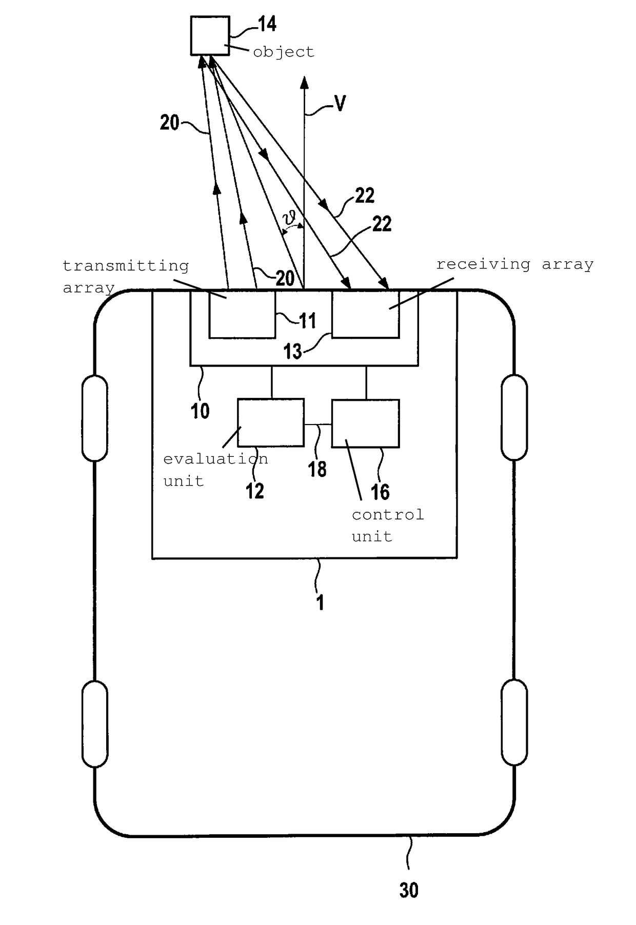
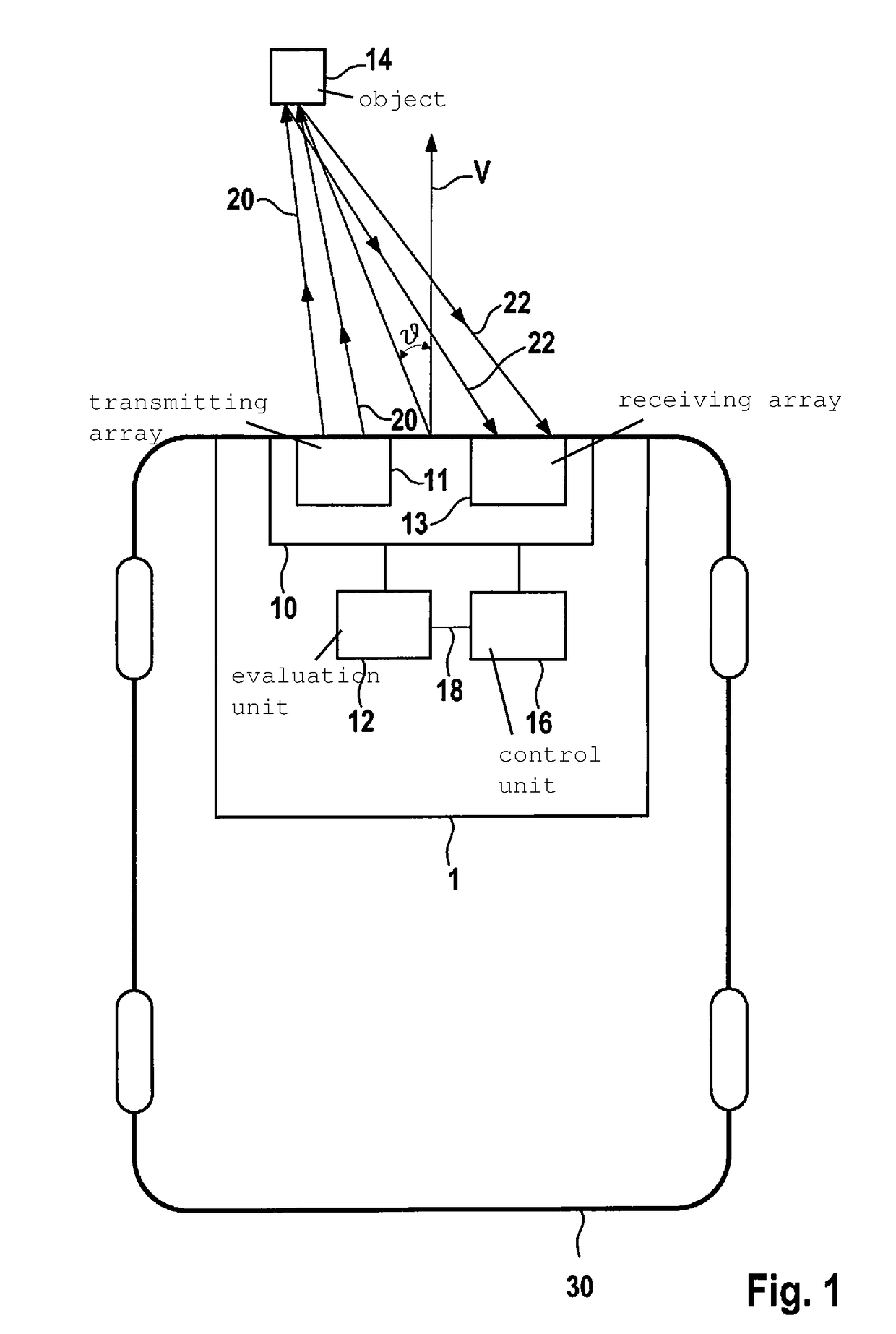
[0039]FIG. 1 shows a schematic block diagram of a MIMO radar device 1 for the decoupled determination of an elevation angle and an azimuth angle θ of an object 14 according to the present invention.

[0040]According to FIG. 1, MIMO radar device 1 is situated in a vehicle 30. Radar device 1 includes a planar antenna array 10, an evaluation unit 12, and a control unit 16. The planar antenna array includes a receiving array 13 made up of multiple receiving antennas and a transmitting array 11 made up of multiple transmitting antennas. Electromagnetic signals 20 are emittable from radar device 1 with the aid of the transmitting antennas. Emitted electromagnetic signals 20 may be reflected on an external object 14, for example, whereby reflected electromagnetic signals 22 result. Reflected electromagnetic signals 22 are receivable with the aid of the receiving antennas of receiving array 13 and may be evaluated with the aid of evaluation unit 12 for the decoupled determination of the eleva...


PUM


Abstract

A MIMO radar device for the decoupled determination of an elevation angle and azimuth angle of an object. The MIMO radar device includes an antenna array including multiple transmitting antennas, whose phase centers are situated spaced apart from one another along a first coordinate direction; and multiple receiving antennas, whose phase centers are situated spaced apart from one another along the first coordinate direction; the phase center of at least one of the transmitting antennas being spaced apart from the phase centers of the remaining transmitting antennas by an offset value along a second coordinate direction; the phase center of at least one of the receiving antennas being spaced apart from the phase centers of the remaining transmitting antennas by the offset value along the second coordinate direction; an evaluation unit to evaluate electromagnetic signals for the decoupled determination of the elevation angle and the azimuth angle of the object.

Description

FIELD[0001]The present invention relates to a MIMO radar device for the decoupled determination of an elevation angle and an azimuth angle of an object and a method for operating the MIMO radar device according to the present invention. The MIMO radar device may be situated in particular in a vehicle, such as a road, rail, air, or water vehicle.BACKGROUND INFORMATION[0002]MIMO stands for “multiple input multiple output” in technical use and refers to a system or method, according to which multiple transmitting antennas and multiple receiving antennas are used for achieving an effect, for example, for transmitting information or, as in the present case, for detecting at least the location of an external object using a radar device. Transmitting antennas are designed in particular for emitting an electromagnetic signal. Receiving antennas are designed in particular for receiving an electromagnetic signal. When “antennas” are referred to here and hereafter, these are to be understood t...

Claims


Application Information

Patent Timeline
Patent Type & Authority Applications(United States)
IPC IPC(8): G01S13/06H01Q21/06H01Q1/32G01S13/93H01Q21/29G01S13/00G01S13/931
CPCG01S13/06G01S13/931G01S13/003G01S2013/9375H01Q21/065H01Q21/296H01Q1/3233G01S7/03G01S13/42H01Q21/293H01Q25/00G01S2013/93271
Inventor LOESCH, BENEDIKTSCHOOR, MICHAEL
Owner ROBERT BOSCH GMBH
Why Eureka
Try Eureka