Optical fiber network for transmitting signals in a robot

Active Publication Date: 2017-10-26
HONDA MOTOR CO LTD
View PDF34 Cites 8 Cited by
  • Summary
  • Abstract
  • Description
  • Claims
  • Application Information

AI Technical Summary

Benefits of technology

[0014]Thereby, only two optical fiber cables (one included in the first optical fiber cable set, the other included in the second optical fiber cable set) pass through each

Problems solved by technology

According to the above arrangement, the optical fiber network does not comprise an optical fiber cable that directly connects the optical transceiver modules whi

Method used


Image

  • Optical fiber network for transmitting signals in a robot
  • Optical fiber network for transmitting signals in a robot
  • Optical fiber network for transmitting signals in a robot

Examples


first embodiment

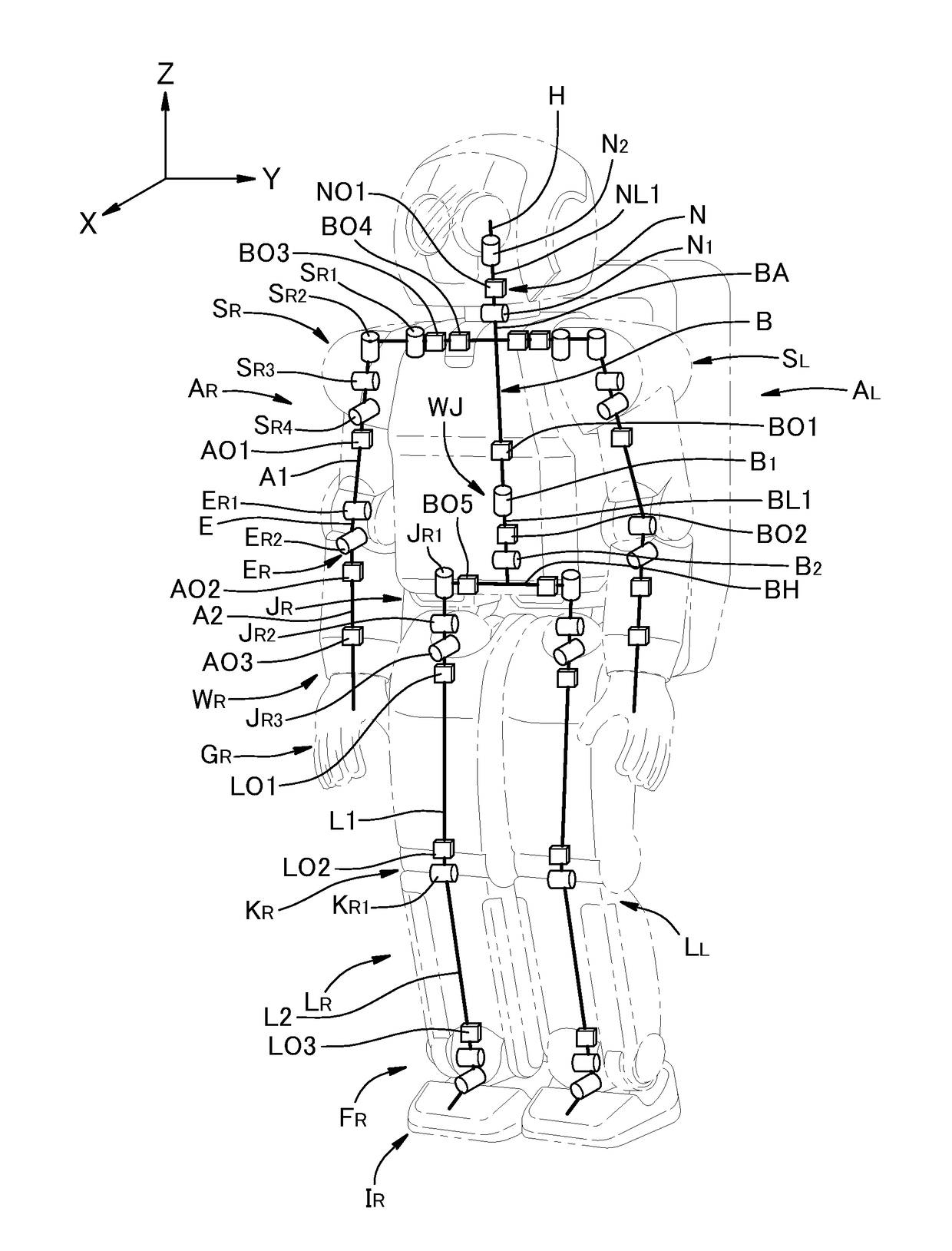
[0044]FIG. 3 is a schematic diagram showing one of the optical fiber networks provided in the robot R according to a first embodiment. As shown in FIG. 3, an optical fiber network 9 includes the optical transceiver modules BO1, BO5, LO1, LO2, and LO3 and optical fiber cables 1, 2, 3, 4, and 5 connecting them. The optical transceiver module BO1 is provided on the torso link BA, and the torso link BA is connected, via the waist joint WJ including the couplings B1 and B2, to the hip link BH which is provided with the optical transceiver module BO5. The hip link BH provided with the optical transceiver module BO5 is connected, via the hip joint JR including the couplings JR1, JR2 and JR3, to the upper link L1 which is provided with the optical transceiver modules LO1 and LO2. The link L1 provided with the optical transceiver modules LO1 and LO2 is connected, via the knee joint KR including the coupling KR1, to the lower link L2 provided with the optical transceiver module LO3. The torso...

second embodiment

[0063]As shown in FIG. 6, an optical fiber network 19 provided in the robot R according to a second embodiment includes the optical transceiver modules BO1, BO3, AO1, AO2, and AO3, and optical fiber cables 11 to 15 connecting them. In this drawing, the controllers and servomotors are omitted. The optical transceiver modules BO1 and BO3 are provided on the torso link BA, which is connected, via the couplings SR1, SR2, SR3, and SR4 of the shoulder joint SR, to the upper link A1 which is provided with the optical transceiver module AO1. The upper link A1 is connected, via the couplings ER1 and ER2 of the elbow joint ER, to the lower link A2 which is provided with the optical transceiver modules AO2 and AO3. The torso link BA, the upper link A1, and the lower link A2 are connected in series via the joints SR and ER including the couplings SR1, SR2, SR3, SR4, ER1, and ER2, and the optical transceiver modules BO1, BO3, AO1, AO2, and AO3 are provided on these links.

[0064]The optical fiber ...

third embodiment

[0072]As shown in FIG. 7, an optical fiber network 29 provided in the robot R according to a third embodiment includes the optical transceiver modules BO1, BO2, BO4, and NO1, and optical fiber cables 21 to 24 connecting them. In this drawing, the controllers and servomotors are omitted. The optical transceiver modules BO1 and BO4 are provided on the torso link BA, which is connected, via the coupling B1 of the waist joint WJ, to the waist link BL1 provided with the optical transceiver module BO2. The torso link BA is also connected, via the coupling N1 of the neck joint N, to the neck link NL1 provided with the optical transceiver module NO1. Thus, the waist link BL1, the torso link BA and the neck link NL1 are connected in series in this order.

[0073]The optical fiber cables 21 to 24 connect the optical transceiver modules BO1, BO2, BO4, and NO1 in a ring. The optical fiber cable 21 connects the optical transmitter TX of the optical transceiver module BO1 with the optical receiver R...


PUM


Abstract

In an optical fiber network for transmitting optical signals in a robot having three or more joints connecting a plurality of links in series such that the links include two end links located at either end and intermediate links provided between the two end links, and the links connected by the joints are moveable relative to each other, a plurality of optical transceiver modules are provided on the links such that at least one optical transceiver module is provided on each link; and a plurality of optical fiber cables connect the optical transceiver modules in a ring; wherein at least one end of each optical fiber cable connecting the optical transceiver modules provided on different links is connected to one of the optical transceiver modules provided on the intermediate links.

Description

TECHNICAL FIELD[0001]The present invention relates to an optical fiber network for transmitting signals in a robot.BACKGROUND ART[0002]It is known to use optical fibers to transmit signals in a robot. For example, JP2015-174208A discloses a robot in which optical communication is performed through a signal line to reduce noise interference caused by capacitive coupling between the signal line and the power line. Particularly, JP2015-174208A discloses disposing an optical communication unit on a pivot shaft of a joint connecting first and second arms (links) of the robot, wherein the optical communication unit includes an optical transmitter and an optical receiver.[0003]A robot typically includes multiple joints connecting multiple links, and it may be conceived to provide controllers on the links of the robot to control the joints. To allow the controllers to operate cooperatively to appropriately control the attitude of the robot, it is necessary to communicably connect the contro...

Claims


Application Information

Patent Timeline
IPC IPC(8): G08C23/04B25J9/00G02B6/44H04B10/40
CPCG08C23/04B25J9/0009G02B6/4463H04B10/40B25J19/0025H04B10/25755H04B10/801G02B6/50
Inventor ISHIZAKI, RYUSUKEIWASAKI, SHINGO
Owner HONDA MOTOR CO LTD
Why Eureka
Try Eureka