System and method for accurate estimation of intentional and unintentional leaks in flow generation systems

Active Publication Date: 2017-11-02
INVENT MEDICAL CORP
View PDF12 Cites 2 Cited by
  • Summary
  • Abstract
  • Description
  • Claims
  • Application Information

AI Technical Summary

Benefits of technology

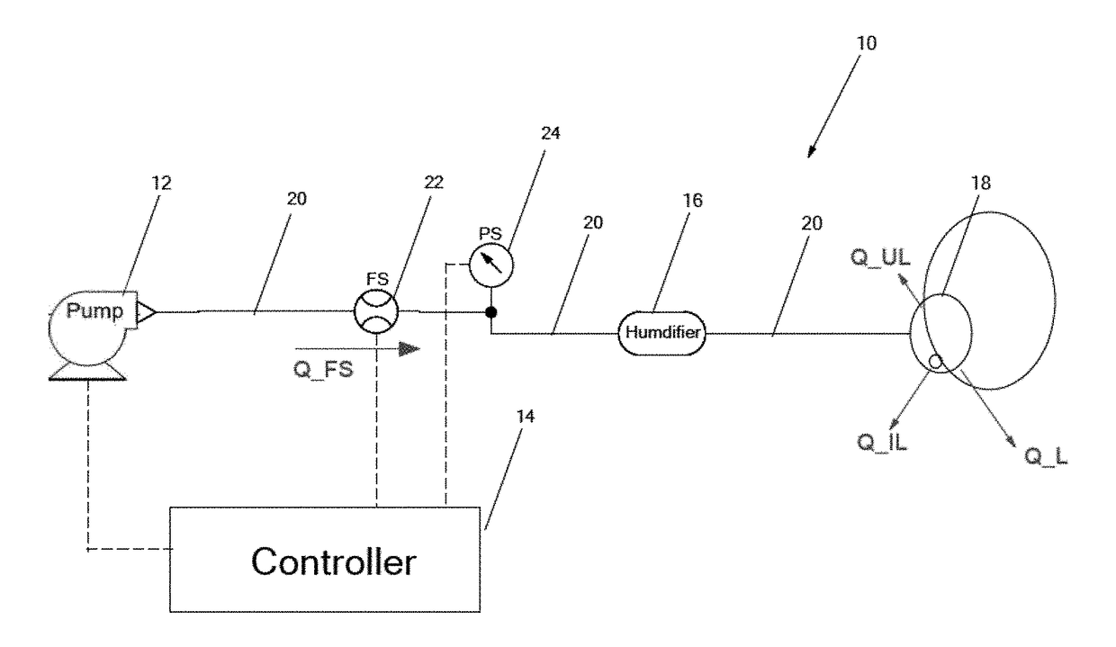
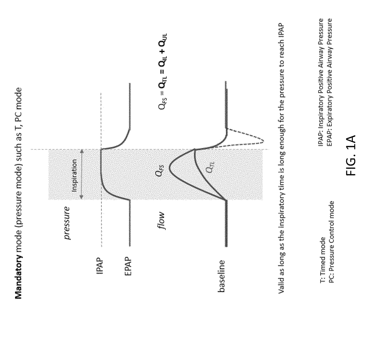
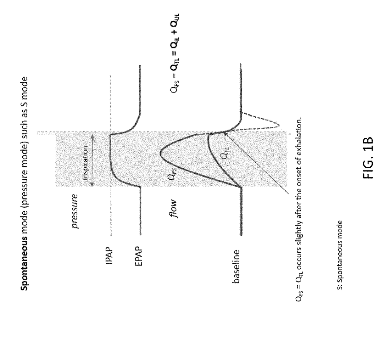
[0007]In one embodiment, a method for accurate leak estimation in a flow generation system includes the steps of measuring a total flow through the flow generation system, measuring a pressure in the primary flow circuit of the flow generation system, determining when the measured pressure is within a predetermined threshold of EPAP, and calculating an intentional leak flowrate and an unintentional leak flowrate based on the relationship QFS(t)=QIL(t)+QUL(t) when the measured pressure is within the predetermined threshold. In one embodiment, the total flow includes a first flow source comprising ambient air and a second flow source comprising pressurized oxygen. In one embodiment, the primary flow circuit comprises a flow sensor for measuring the total flow, an airflow generator and a patient interface connection. In one embodiment, PPS(t)≅EPAP when PPS(t) is within 0.5 cmH2O from EPAP. In one embodiment, PPS(t)≅EPAP when PPS(t) is within 0.2 cmH2O from EPAP. In one embodiment, PPS(t)≅EPAP when PPS(t) is within 0.1 cmH2O from EPAP. In one embodiment, PPS(t)≅EPAP when PPS(t) is within 1 cmH2O from EPAP. In one embodiment, the method includes

Problems solved by technology

When any patient interface such as patient tubing, masks, mouth piece, etc. is used on a flow generation system such as a ventilator, leak is inherent to the system.
However, there will be unintentional leaks as well, typically from masks that are not well fitted, dislodging of masks due to patient's movement, or other causes.
Since patient flow can assumed be to be zero at the end of exhalation, any difference between actual patient flow and original baseline flow may represent unintentional leak.
When the leak estimate is not accurate, ventilators canno

Method used


Image

  • System and method for accurate estimation of intentional and unintentional leaks in flow generation systems
  • System and method for accurate estimation of intentional and unintentional leaks in flow generation systems
  • System and method for accurate estimation of intentional and unintentional leaks in flow generation systems

Examples


Example

[0021]It is to be understood that the figures and descriptions of the present invention have been simplified to illustrate elements that are relevant for a more clear comprehension of the present invention, while eliminating, for the purpose of clarity, many other elements found in systems and methods for accurately estimating both intentional and unintentional leaks in flow generation systems. Those of ordinary skill in the art may recognize that other elements and / or steps are desirable and / or required in implementing the present invention. However, because such elements and steps are well known in the art, and because they do not facilitate a better understanding of the present invention, a discussion of such elements and steps is not provided herein. The disclosure herein is directed to all such variations and modifications to such elements and methods known to those skilled in the art.

[0022]Unless defined otherwise, all technical and scientific terms used herein have the same m...


PUM


Abstract

In one embodiment, a method for accurate leak estimation in a flow generation system includes measuring a total flow through the flow generation system, measuring a pressure in in the primary flow circuit of the flow generation system, determining when the measured pressure is within a predetermined threshold of EPAP, and calculating an intentional leak flowrate and an unintentional leak flowrate based on the relationship QFS(t)=QIL(t)+QUL(t) when the measured pressure is within the predetermined threshold. In another embodiment, a flow generation system includes in one embodiment an airflow generator connected in-line to a flow sensor, a pressure sensor and a patient interface connection by a first gas flow circuit, and a controller electrically coupled to the airflow generator, the flow sensor and the pressure sensor. The controller sends a control signal to the airflow generator based on a first flow value measured from the flow sensor and an unintentional leak flow value that is derived from a proportional relationship with an intentional leak flow value.

Description

CROSS-REFERENCE TO RELATED APPLICATIONS[0001]This application claims priority to U.S. provisional application No. 62 / 328,675 filed on Apr. 28, 2016 incorporated herein by reference in its entirety.BACKGROUND OF THE INVENTION[0002]Flow generation systems can be generally described as systems that generate a gaseous flow, for example airflow or a blend of ambient air and oxygen. A ventilator is one example of a flow generation system. A ventilator is a piece of medical equipment that delivers a flow of gas, such as a blend of oxygen and ambient air to the airway of a patient to assist in or substitute a patient's breathing. Many ventilators deliver a blend of oxygen and air so that the patient receives a target oxygen concentration greater than that of ambient air. Generally, ventilators utilize a combination of single-use or reusable disposable components for the patient interface (e.g. a mask or mouthpiece connected to flexible tubing) and non-disposable capital equipment (e.g. air ...

Claims


Application Information

Patent Timeline
IPC IPC(8): A61M16/00A61M16/10A61M16/20G01M3/26A61M16/12A61M16/16
CPCA61M16/0069G01M3/26A61M16/0051A61M16/16A61M16/1005A61M16/125A61M2202/0208A61M16/208A61M2016/0027A61M2016/0033A61M2230/40A61M2205/50A61M2205/15A61M16/1055A61M16/1045G01M3/28A61M2016/0039A61M16/0672A61M16/026A61M2202/0007
Inventor CHANG, SAMUEL M.NGUYEN, NHIEN M.
Owner INVENT MEDICAL CORP
Why Eureka
Try Eureka