Variable rate display interfaces

a display interface and variable rate technology, applied in the field of communication to and from displays, can solve the problems of size penalties, high cost, and commercially impractical approaches, and achieve the effects of increasing the frequency of reverse data, increasing the bandwidth of each high-speed reverse data transfer, and increasing the dsi clock speed

Active Publication Date: 2017-11-02
QUALCOMM INC
View PDF18 Cites 10 Cited by
  • Summary
  • Abstract
  • Description
  • Claims
  • Application Information

AI Technical Summary

Benefits of technology

[0005]Aspects disclosed in the detailed description include variable rate display interfaces. In an exemplary aspect, a high-speed reverse data transfer is enabled over plural lanes of a display serial interface (DSI) bus during blanking periods. Further increases in bandwidth of each high-speed reverse data transfer may be achieved by increasing DSI clock speed during the blanking periods. Since a display relies on a host clock to send reverse data, the frequency of the reverse data is increased, which effectively increases the bandwidth of reverse channel lanes. By increasing the reverse bandwidth over existing pins associated with data lanes in the DSI bus, more data may be transferred to the host, including raw touch / stylus data rather than processed data. The raw data may then be processed by the host's relatively powerful processors. By shifting the processing to the host, the need for a powerful touch screen controller (TSC) and / or a powerful touch display driver integrated circuit (TDDI) may be avoided. Likewise, memory requirements for any such TSC or TDDI may be minimized

Problems solved by technology

While adding data lanes (sometimes called auxiliary lanes) through the addition of pins is one solution to provide additional reverse channel bandwidth, such approach is commercially impractical in view of the size penalties and expense associated with such additional pins.

Method used


Image

  • Variable rate display interfaces
  • Variable rate display interfaces
  • Variable rate display interfaces

Examples


Embodiment Construction

[0019]With reference now to the drawing figures, several exemplary aspects of the present disclosure are described. The word “exemplary” is used herein to mean “serving as an example, instance, or illustration.” Any aspect described herein as “exemplary” is not necessarily to be construed as preferred or advantageous over other aspects.

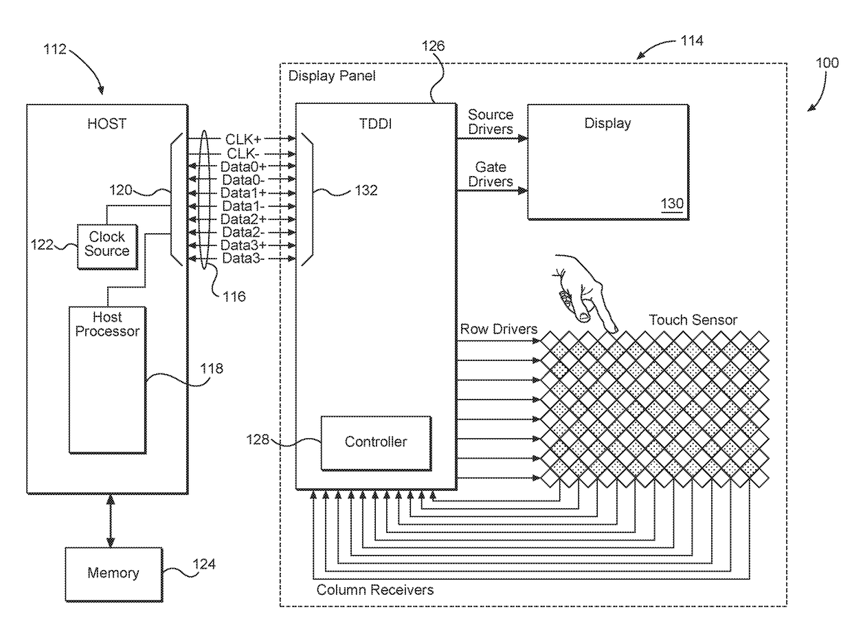
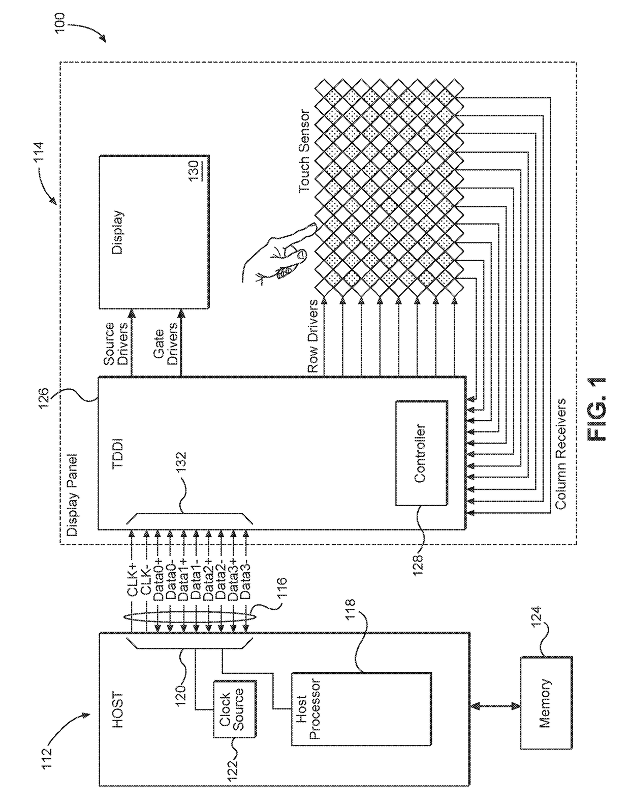
[0020]Aspects disclosed in the detailed description include variable rate display interfaces. In an exemplary aspect, a high-speed reverse data transfer is enabled over plural lanes of a display serial interface (DSI) bus during blanking periods. Further increases in bandwidth of each high-speed reverse data transfer may be achieved by increasing DSI clock speed during the blanking periods. Since a display relies on a host clock to send reverse data, the frequency of the reverse data is increased, which effectively increases the bandwidth of reverse channel lanes. By increasing the revere bandwidth over existing pins in the DSI bus, more data may be t...


PUM


Abstract

Variable rate display interfaces are disclosed. In an exemplary aspect, a high-speed reverse data transfer is enabled over plural lanes of a display serial interface (DSI) bus during blanking periods. Further increases in bandwidth of each high-speed reverse data transfer may be achieved by increasing DSI clock speed during the blanking periods. Since a display relies on a host clock to send reverse data, the frequency of the reverse data is increased, which effectively increases the bandwidth of reverse channel lanes. By increasing the reverse bandwidth over existing pins in the DSI bus, more data may be transferred to the host, including raw touch / stylus data rather than processed data. The raw data may then be processed by the host's relatively powerful processors. By shifting the processing to the host, the need for a powerful touch screen controller (TSC) and / or a powerful touch display driver integrated circuit (TDDI) may be avoided.

Description

BACKGROUNDI. Field of the Disclosure[0001]The technology of the disclosure relates generally to communications to and from displays on computing devices.II. Background[0002]Computing devices have become common in almost every facet of everyday activity. Almost every computing device has some form of user interface. Most such user interfaces include some way a user can provide input to the computing device as well as a display through which the user can receive output from the computing device. A relatively recent trend is the incorporation of a touch screen display that allows the input and the output functions to be combined in a single device.[0003]Various specifications have been created that control how data is sent from a control system (sometimes referred to as a host) to a display device. When the display device was a simple device, the majority of the data was generated in a forward direction from the control system to the display device. That is, video data was sent from th...

Claims


Application Information

Patent Timeline
Patent Type & Authority Applications(United States)
IPC IPC(8): G06F3/041G06F1/08G06F3/00G06F13/42
CPCG06F3/0416G06F3/005G06F1/08G06F13/4291G06F13/4273
Inventor POURBIGHARAZ, FARIBORZ
Owner QUALCOMM INC
Why Eureka
Try Eureka