Ultrasonic transducer and method for manufacturing the same

Inactive Publication Date: 2017-11-02
CANON KK
View PDF7 Cites 2 Cited by
  • Summary
  • Abstract
  • Description
  • Claims
  • Application Information

AI Technical Summary

Benefits of technology

[0008]In the aspects of the present invention described above, the protective film having the acoustic matching layer on one side thereof is placed such that the acoustic matching layer tightly adheres to, or is in contact with, the ultrasonic device. More specifically, the continuous protective film having the acoustic matching lay

Problems solved by technology

When a large number of very small devices are mounted on a considerably uneven surface to form a transducer, it is di

Method used


Image

  • Ultrasonic transducer and method for manufacturing the same
  • Ultrasonic transducer and method for manufacturing the same
  • Ultrasonic transducer and method for manufacturing the same

Examples


Example

First Embodiment

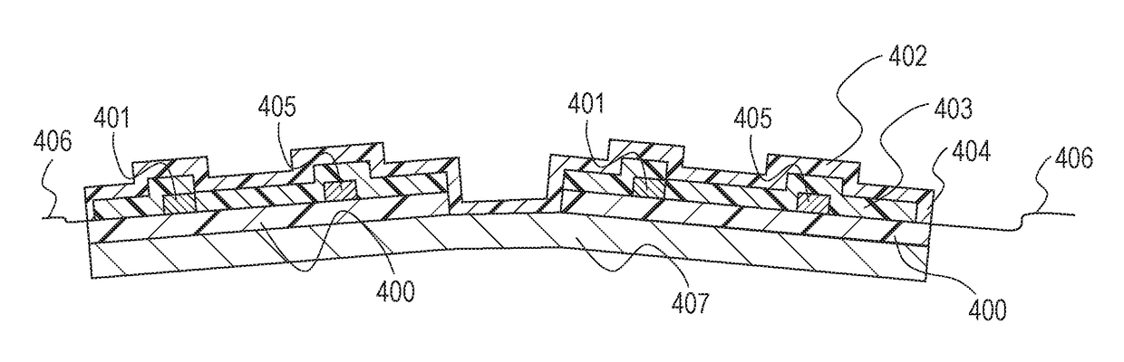
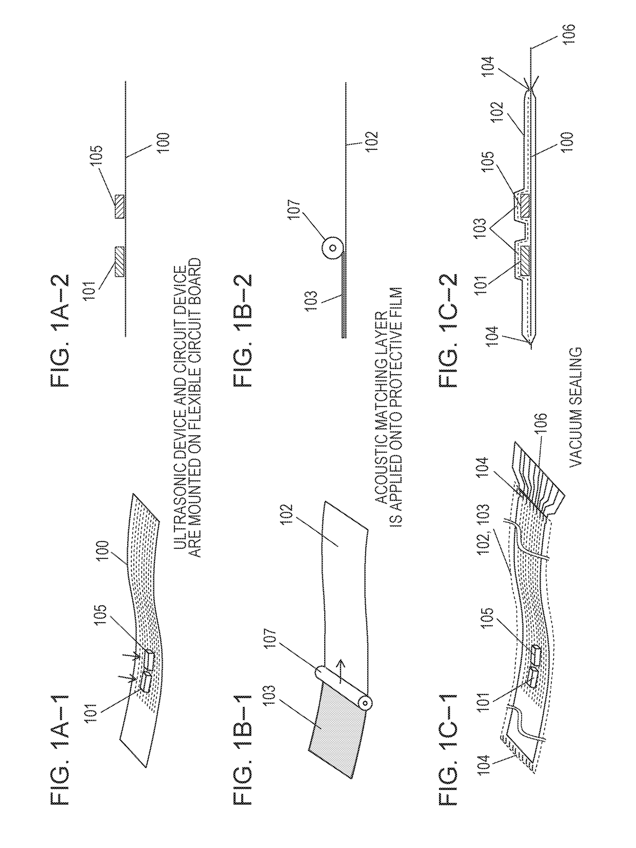
[0015]A configuration of an ultrasonic transducer and a method for manufacturing the ultrasonic transducer according to a first embodiment of the present invention will be described. FIGS. 1A-1, 1B-1, and 1C-1 are perspective views illustrating an ultrasonic transducer manufacturing method according to the present embodiment. FIGS. 1A-2, 1B-2, and 1C-2 are cross-sectional views of FIGS. 1A-1, 1B-1, and 1C-1. In the drawings, reference numeral 100 denotes a substrate having flexibility, reference numeral 101 denotes a transmitting and / or receiving ultrasonic device, reference numeral 102 denotes a protective film, and reference numeral 103 denotes an acoustic matching layer. Reference numeral 104 denotes a sealed portion of the protective film 102, reference numeral 105 denotes a circuit device (e.g., IC device or electrical circuit device, such as a resistor or capacitor), and reference numeral 106 denotes an electrode extended portion where electrodes are extended t...

Example

Second Embodiment

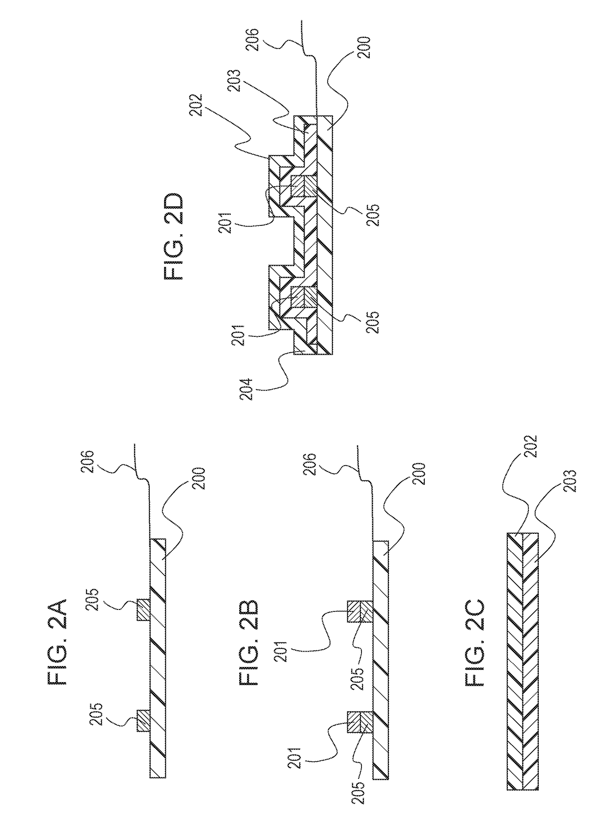
[0031]An ultrasonic transducer manufacturing method according to a second embodiment of the present invention will be described. FIGS. 2A to 2D are schematic cross-sectional views of an ultrasonic transducer according to the present embodiment. The present embodiment deals with a method for manufacturing an ultrasonic transducer in which a circuit device is disposed between a substrate and an ultrasonic device. The following mainly describes differences from the first embodiment, and the description of common elements will be omitted or simplified.

[0032]In FIGS. 2A to 2D, reference numeral 200 denotes a flexible circuit board having flexibility, reference numeral 201 denotes a transmitting and / or receiving ultrasonic device, reference numeral 202 denotes a protective film, reference numeral 203 denotes an acoustic matching layer, reference numeral 204 denotes a sealed portion of the protective film 202, reference numeral 205 denotes a circuit device (e.g., IC device...

Example

Third Embodiment

[0034]An ultrasonic transducer manufacturing method according to a third embodiment of the present invention will be described. FIGS. 3A to 3D are schematic cross-sectional views of an ultrasonic transducer according to the present embodiment. The present embodiment deals with an ultrasonic transducer in which the substrate has ultrasonic devices on one of two principal surfaces thereof and circuit devices on the other principal surface (back surface) thereof. The following mainly describes differences from the first embodiment, and the description of common elements will be omitted or simplified.

[0035]In FIGS. 3A to 3D, reference numeral 300 denotes a flexible circuit board having flexibility, reference numeral 301 denotes a transmitting and / or receiving ultrasonic device, reference numeral 302 denotes a protective film, reference numeral 303 denotes an acoustic matching layer, and reference numeral 304 denotes a sealed portion of the protective film 302. Reference ...


PUM


Abstract

In an ultrasonic transducer manufacturing method, an ultrasonic device is mounted on a substrate, and a protective film having an acoustic matching layer thereon is prepared. Then, the protective film having the acoustic matching layer thereon is placed over the ultrasonic device such that the acoustic matching layer is in contact with the ultrasonic device.

Description

BACKGROUND OF THE INVENTIONField of the Invention[0001]The present invention relates to an ultrasonic transducer that performs at least one of transmission and reception of ultrasonic waves, and to a method for manufacturing the ultrasonic transducer.Description of the Related Art[0002]There are converters called ultrasonic transducers that are capable of performing a conversion between an electrical signal and an ultrasonic signal. The ultrasonic transducers are applied to flaw detection, exploration, and communication techniques, and are used in a wide range of applications in industrial and medical fields. Examples of ultrasonic devices used in the ultrasonic transducers include piezoelectric devices using piezoelectric elements, and capacitive devices including electrodes above and below a cavity. Such ultrasonic devices are connected to wires and electrical circuits to form an ultrasonic transducer which is designed to control the electrical insulation, the efficiency of transm...

Claims


Application Information

Patent Timeline
IPC IPC(8): H01L41/08H01L41/23B06B1/10H01L41/27B06B1/06
CPCH01L41/0825B06B1/06H01L41/27H01L41/23B06B1/10B06B1/0292H10N30/883H10N30/02H10N30/1071H10N30/05
Inventor TOMIYOSHI, TOSHIO
Owner CANON KK
Why Eureka
Try Eureka