
Resiliency Controller for Voltage Regulation in Microgrids

Active Publication Date: 2017-11-02
NEC CORP
View PDF2 Cites 35 Cited by
  • Summary
  • Abstract
  • Description
  • Claims
  • Application Information

AI Technical Summary

Benefits of technology

The patent describes a method and system for controlling the voltage fluctuations in a microgrid that includes multiple distributed generators (DGs). The system includes a resiliency controller with a voltage control module that collects measurement data from the microgrid and uses a reactive power estimator to calculate the amount of reactive power needed for each DG. The system also includes a dynamic droop control unit that distributes the necessary reactive power to each DG to ensure a stable and reliable connection to the grid. The technical effects of the patent are improved stability and efficiency of the microgrid, as well as better utilization of the DGs' potential for power output.

Problems solved by technology

With the increasing penetration of renewables, the traditional distribution system design philosophy is being challenged.
One concern is the voltage rise challenge caused by reverse power flow when the solar photovoltaic (PV) generation substantially exceeds the load demand.
Existing solutions of these voltage issues include either restricting PV output or tripping it with over-voltage / under-voltage relays, both of which are disruptive.
Nonetheless, the negative impact of PV grid integration has drawn concerns.
When PV generation substantially exceeds local load at the point of common coupling (PCC), surplus power from PV flows back to the grid and produces reverse power flows, which may cause the voltage rise challenge mentioned above.
Further, due to high variability of solar energy availability (e.g., cloud transient effect), PV generation can fluctuate at a very high ramping rate, thus leading to power quality and even voltage stability issues.
The aforementioned voltage challenges make it difficult for the distribution utilities to operate their feeders without violating the voltage limits stipulated by local standards.

Method used


Image

  • Resiliency Controller for Voltage Regulation in Microgrids
  • Resiliency Controller for Voltage Regulation in Microgrids
  • Resiliency Controller for Voltage Regulation in Microgrids

Examples


Embodiment Construction

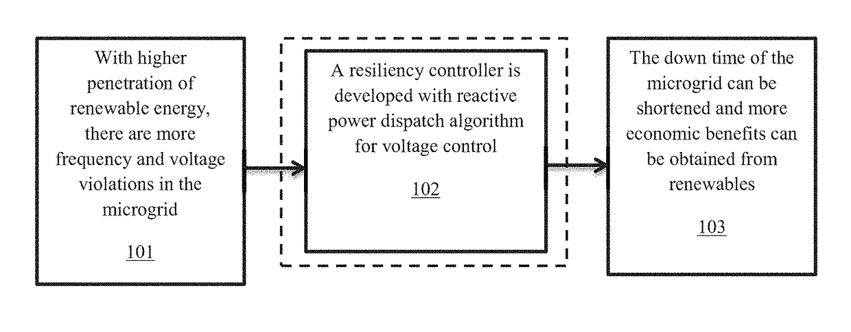
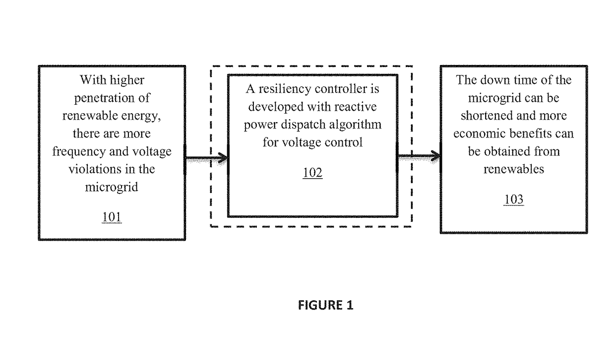
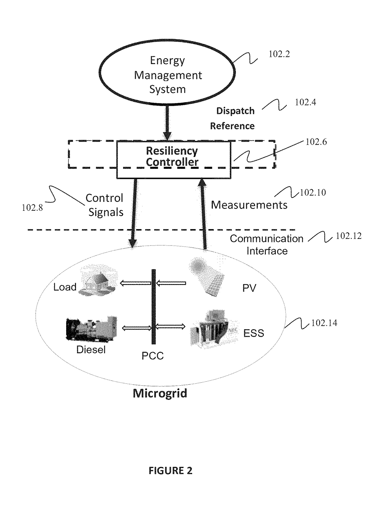
[0022]In one aspect, the method, system, and non-transitory computer-readable storage medium include a framework for distribution network voltage regulation by integrating a solar photovoltaic (PV) system with a distributed energy storage system (ESS) and adaptively dispatching the ESS. In the exemplary embodiments of the present invention, the voltage and current phasors at the point of common coupling (PCC) are continuously monitored to establish a real-time Thevenin equivalent of the distribution grid. Based on this equivalent, the maximum and minimum power injections allowed at PCC are continuously tracked. The voltage violation margins at PCC are calculated and the ESS is controlled adaptively to prevent the occurrence of one or more voltage violations. The proposed methods and systems can also be used to mitigate the effects of sudden changes in PV outputs.

[0023]In one aspect, the method, system, and non-transitory computer-readable storage medium include a resiliency controll...


PUM


Abstract

A computer-implemented method for controlling voltage fluctuations of a microgrid including a plurality of distributed generators (DGs) is presented. The computer-implemented method includes collecting, by a resiliency controller including at least a voltage control module, measurement data from the microgrid, using, by a reactive power estimator, reactive power estimations to calculate an amount of reactive power for each of the DGs, and using a dynamic droop control unit to distribute the reactive power to each of the DGs of the microgrid.

Description

RELATED APPLICATION INFORMATION[0001]This application claims priority to Provisional Application No. 62 / 330,457, filed on May 2, 2016, incorporated herein by reference in its entirety.BACKGROUNDTechnical Field[0002]The present invention relates to power systems and, more particularly, to a resiliency controller for voltage regulation in micro-grids.Description of the Related Art[0003]With the increasing penetration of renewables, the traditional distribution system design philosophy is being challenged. One concern is the voltage rise challenge caused by reverse power flow when the solar photovoltaic (PV) generation substantially exceeds the load demand. Existing solutions of these voltage issues include either restricting PV output or tripping it with over-voltage / under-voltage relays, both of which are disruptive.[0004]Penetration of renewable energy sources (RESs) in power systems has been increasing dramatically during the last few years. The PV system is the most commonly obser...

Claims


Application Information

Patent Timeline
IPC IPC(8): H02J3/38G05B15/02H02J3/46H02J13/00
CPCH02J3/381H02J13/0006H02J3/46G05B15/02H02J3/12H02J3/18H02J3/50Y02E40/30Y04S10/123H02J2203/20H02J2300/20H02J13/00017H02J13/00034Y02E40/70Y02E60/00Y04S40/20Y04S10/22Y04S40/124
Inventor GUO, FENGSHARMA, RATNESH
Owner NEC CORP
Learn More