
Transmission

a transmission and q-factor technology, applied in the direction of toothed gearings, belts/chains/gearrings, mechanical instruments, etc., can solve the problems of increased risk, inside pedal touch down, and large q-factor, and achieve the effect of reducing the transmission dimension

Inactive Publication Date: 2017-11-09
MOVE BIKES GMBH
View PDF0 Cites 14 Cited by
  • Summary
  • Abstract
  • Description
  • Claims
  • Application Information

AI Technical Summary

Benefits of technology

The invention relates to a control housing for a transmission, which includes a wall segment that separates the sun wheel, planet gear, and crank, providing protection against external influences and allowing for a compact design. A linear guide is located on the outer side of the wall segment, contributing to a narrowest possible transmission design in the axial direction of the main shaft. The guide rail and carriage engage in the axial direction with a toothed ring, further reducing the dimensions of the transmission. Alternatively, the guide rail may execute an alternating movement about the main shaft center axis. The invention also includes a rail element with two guide rails and one carriage, providing better stability and reduced risk of jamming or skewing.

Problems solved by technology

It has proven to be a drawback in the known transmission that the pedaling is felt as being spongy on account of the free running guide roller and furthermore the known design with a crank arm head mounted on two sides results in a large Q-factor.
This increases the risk on tight curves taken at high speed that the inside pedal will touch down, and too large a Q-factor is harmful for ergonomic reasons.

Method used


Image

  • Transmission
  • Transmission
  • Transmission

Examples


Embodiment Construction

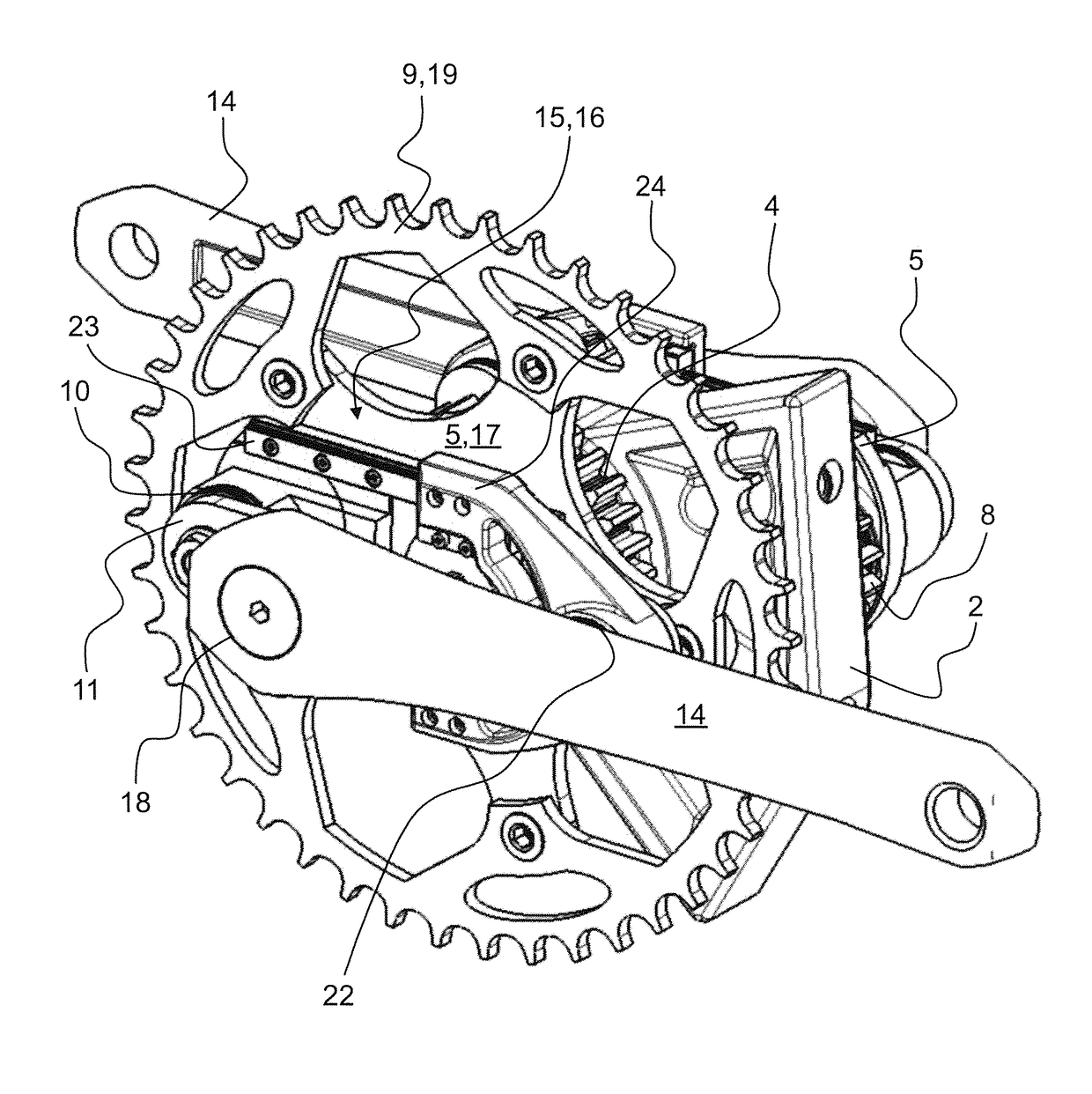
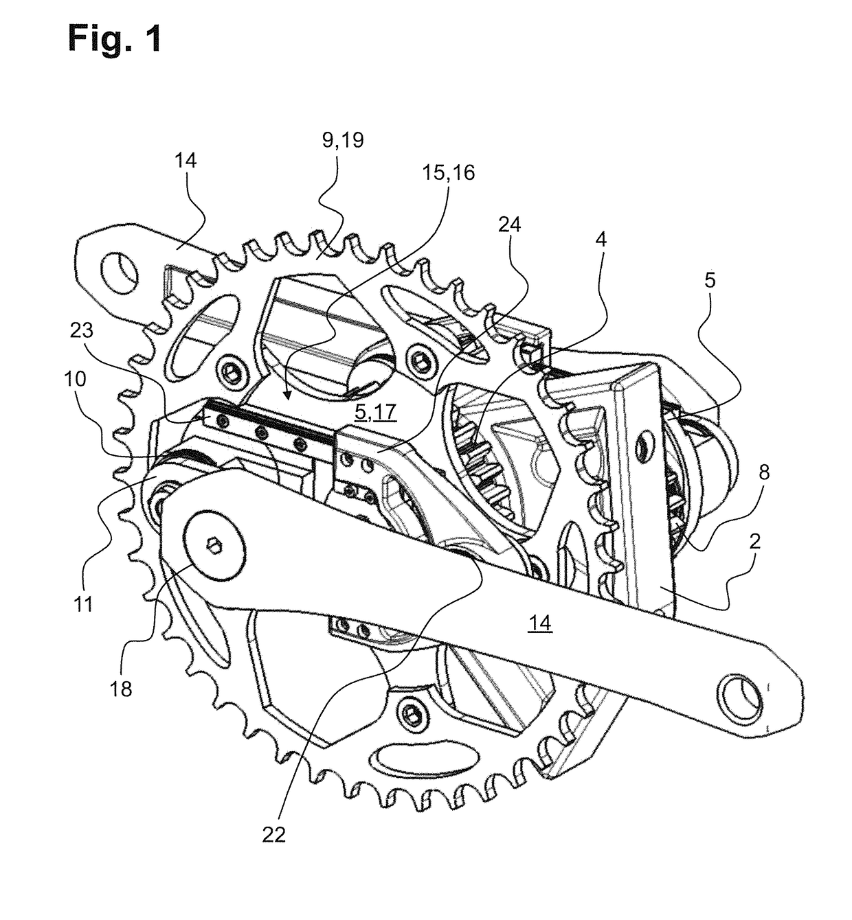
[0032]FIG. 1 shows a perspective view of the transmission according to the invention, which may be secured via a housing 2 to a frame or beam, not shown. The transmission is built as a mirror image on either side of the housing 2, with the sole difference that a force transmission means 9 in the form of a toothed ring 19 is present in the section situated in front in the plane of the drawing, which is mounted on a control housing 5 in a rotationally fixed manner. On the toothed ring 19 there may be placed, for example, a chain (not shown), which in turn transmits a rotary movement of the control housing 5 and thus also of the toothed ring 19.

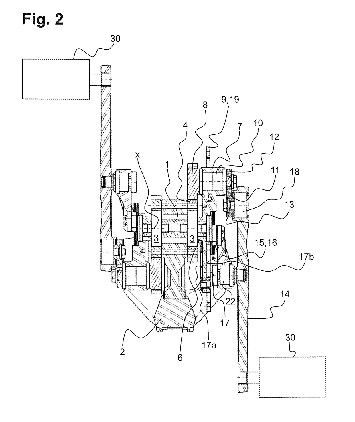
[0033]Through the housing 2 there runs a main shaft 1, visible in the cross section in FIG. 2, being mounted in rotational manner with respect to the housing 2 by two main shaft bearings 3 at a spacing from each other in the axial direction. The main shaft 1 is firmly connected at both ends to a control housing 5.

[0034]Furthermore, on opposite s...


PUM


Abstract

A transmission for a system, in which a directed force is introduced eccentrically with respect to a main shaft of the transmission, comprising the main shaft which is rotatably mounted in relation to a stationary housing by a main shaft bearing, a sun gear which is fixedly connected to the housing being arranged concentrically around the main shaft, and at least one control housing that rotates around the housing, wherein the first section thereof acts on the main shaft in a rotationally fixed manner and a planetary wheel is rotatably mounted by a first rotary bearing on the second section thereof, said planetary gear meshing with the sun gear. According to the invention, a force transmission means is fastened to the control housing and a drive crank rigidly engages the first end on the planetary wheel, wherein a second end of the drive crank is mounted in an articulated manner on a crank arm, said crank arm being supported in relation to the control housing by a movable coupling means. The aim of the invention was to provide a transmission having structural dimensions which are as compact as possible in the axial direction of the main shaft. Said aim is achieved in that the movable coupling means is a linear guide which absorbs tilting torques transmitted by the crank arm.

Description

FIELD OF THE INVENTION[0001]The invention concerns a transmission in which a directed force is introduced eccentrically to a main shaft of the transmission.BACKGROUND OF THE INVENTION[0002]Such transmissions may be built in particular in bicycles and ensure an amplification of the torque through the force applied by the bicycle rider. In this application, the housing of the transmission is adapted to a frame component and the force transmission means, such as a toothed ring, transmits the torque generated by the bicycle rider via a chain to the rear wheel. However, the transmission according to the invention may likewise be provided, for example, for wind power plants with vertically placed axles of rotation.[0003]A prior art of this kind is formed by DE 10 2010 033 211 B4 with a bicycle transmission, in which the sun wheel, the planet gear and the crank are arranged inside a common crank housing and the crank arm is braced by means of a guide roller against a guide rail likewise ar...

Claims


Application Information

Patent Timeline
Patent Type & Authority Applications(United States)
IPC IPC(8): B62M3/06F16H1/28B62M11/02
CPCB62M3/06F16H1/28B62M11/02B62M11/145
Inventor SPROTE, TOBIASBURRE, DOMINIKROCHLITZER, MARCUSLEGENMAJER, JULIUS
Owner MOVE BIKES GMBH
Learn More