Electricity storage module

a technology of electricity storage module and heat dissipation property, which is applied in the direction of electrochemical generators, cell components, batteries, etc., to achieve the effect of improving the heat dissipation property and reliable cooling of electricity storage elements

Active Publication Date: 2017-11-09
AUTONETWORKS TECH LTD +2
View PDF0 Cites 0 Cited by
  • Summary
  • Abstract
  • Description
  • Claims
  • Application Information

AI Technical Summary

Benefits of technology

[0022]According to the above-described aspect, air can flow through the gaps formed between the outer surfaces of the electricity storage elements and the inner walls of the cavities. As a result, air that has flowed into the holding member through the outer wall opening portions comes in...

Problems solved by technology

Also, the outer surfaces of the electricity storage elements face the exterior of the holding member through the outer wall opening portion...

Method used


Image

  • Electricity storage module
  • Electricity storage module
  • Electricity storage module

Examples


embodiment 2

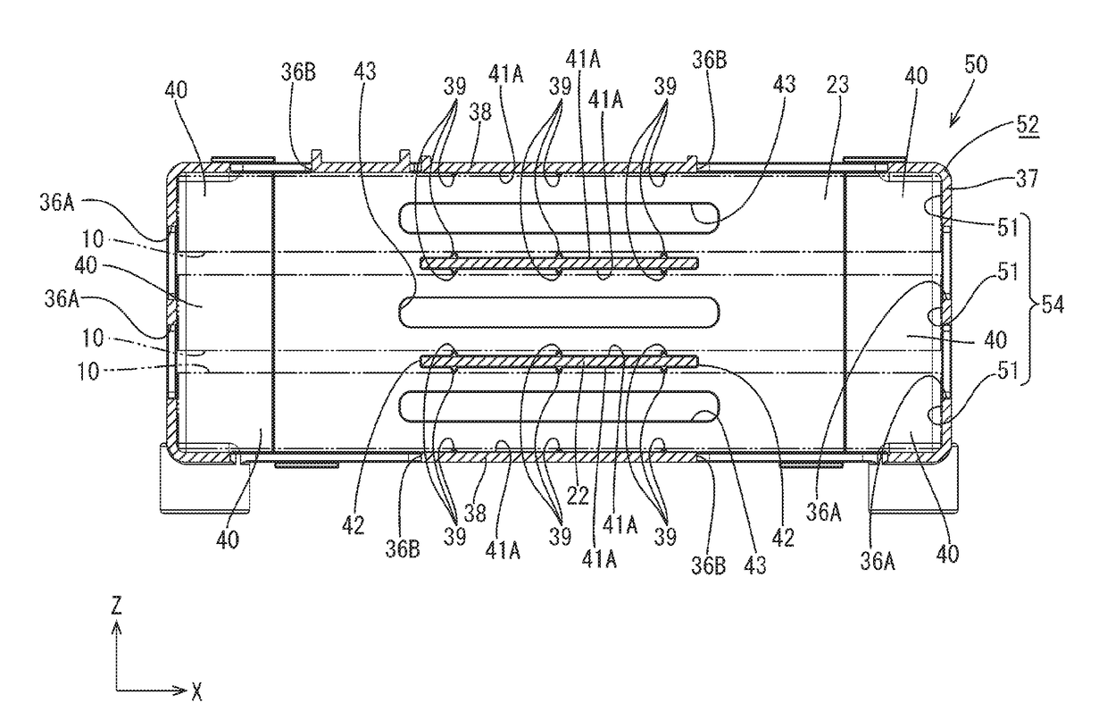
[0082]Next, an electricity storage module 50 according to Embodiment 2 of the present invention will be described with reference to FIG. 16. In the present embodiment, multiple cavities 51 are formed in alignment in three levels in the vertical direction. Accordingly, an arrangement is achieved in which three electricity storage elements 10 are arranged in alignment in the vertical direction. Configurations other than that described above are approximately the same as those of Embodiment 1, and therefore identical members are denoted by identical reference numerals, and redundant description is not included.

[0083]The electricity storage module 50 according to the present embodiment includes: multiple electricity storage elements 10; and a holding member 52 formed by aligning multiple cavities 51 in which the multiple electricity storage elements 10 are stored, wherein an outer wall of the holding member 52 has outer wall opening portions 36A and 36B that communicate with the multipl...


PUM


Abstract

An electricity storage module includes: multiple electricity storage elements; and a holding member formed by aligning multiple cavities in which the multiple electricity storage elements are stored, wherein an outer wall of the holding member has outer wall opening portions through which the multiple cavities communicate with the exterior, and outer surfaces of the multiple electricity storage elements stored in the multiple cavities are exposed to the exterior from the outer wall through the outer wall opening portions, and the holding member has a first cavity column in which cavities among the multiple cavities are aligned in two levels in an alignment direction, and a second cavity column in which cavities among the multiple cavities are aligned in two levels in the alignment direction at positions shifted in a direction intersecting with the alignment direction.

Description

CROSS-REFERENCE TO RELATED APPLICATIONS[0001]This application is the U.S. national stage of PCT / JP2015 / 082988 filed Nov. 25, 2015, which claims priority of Japanese Patent Application No. JP 2014-238873 filed Nov. 26, 2014.TECHNICAL FIELD[0002]The present invention relates to an electricity storage module.BACKGROUND[0003]Conventionally, an electricity storage module formed by aligning multiple electricity storage elements has been known as a power source for an electric automobile, a hybrid car, or the like (see JP 2010-225449M. In this electricity storage module, electrodes of electricity storage elements are connected to each other in a state in which the multiple electricity storage elements are arranged aligned in a column.[0004]Electricity storage elements generate heat during charging and discharging. For this reason, in a configuration in which multiple electricity storage elements are aligned in a column as in the electricity storage module disclosed in the conventional tech...

Claims


Application Information

Patent Timeline
IPC IPC(8): H01M10/6556H01M2/10H01G11/10H01M10/625H01G11/18H01G11/76H01G11/82H01M50/204
CPCH01M10/6556H01G11/10H01G11/82H01M2220/20H01G11/18H01M2/10H01M10/625H01G11/76H01G2/04H01G2/08H01M10/613H01M10/6562Y02T10/70Y02E60/10H01M50/204
Inventor SUMIDA, TATSUYAMORITA, KYOHEI
Owner AUTONETWORKS TECH LTD
Why Eureka
Try Eureka