Replacement mitral valves

a technology of replacement leaflets and mitral valves, which is applied in the field can solve the problems of obstructing blood flow, mitral stenosis, and insufficiency, and achieves the effects of minimizing deformation of replacement leaflet alignment, and reducing the spring constan

Active Publication Date: 2017-11-16
CEPHEA VALVE TECH
View PDF4 Cites 115 Cited by
  • Summary
  • Abstract
  • Description
  • Claims
  • Application Information

AI Technical Summary

Benefits of technology

[0010]This and other embodiments can include one or more of the following features. A ventricular end of the central annular member can have a smaller diameter than a diameter of the atrial end of the central annular member. The diameter of the ventricular end can be between 25 mm and 30 mm, and the diameter of the atrial end is between 30 mm and 35 mm. The central annular member can include a plurality of linear posts extending from an atrial end to a ventricular end and a plurality of zig-zag circumferential members extending circumferentially therearound. The central annular member can have a lower spring constant than the strut frame. The strut frame can have a higher spring constant than the anchor assembly. The central annular member can include a suspension. The central annular member and the anchor assembly can be connected together with couplers. The central annular member and the annular strut frame can be connected together with couplers. The central annular member can be configured to minimize deformation of replacement leaflet alignment in response to deformation of an expandable anchor. The device can be configured to self-expand from a constrained configuration to an expanded configuration. The device can be configured to foreshorten upon expansion of the atrial anchor, ventricular anchor, and central portion from the constrained configuration to the expanded configuration.
[0012]This and other embodiments can include one or more of the following features. The suspension can have a lower spring constant than the strut frame. The strut frame can have a higher spring constant than the anchor assembly. The suspension can include a plurality of springs. The springs can be leaf springs. The suspension and the anchor assembly can be connected together with couplers. The suspension and the annular strut frame can be connected together with couplers. The suspension can be configured to minimize deformation of replacement leaflet alignment in response to deformation of an expandable anchor. The device can be configured to self-expand from a constrained configuration to an expanded configuration. The device can be configured to foreshorten upon expansion of the atrial anchor, ventricular anchor, and central portion from the constrained configuration to the expanded configuration.
[0026]In general, in one embodiment, a replacement mitral valve includes an anchor assembly comprising a ventricular anchor, an annular central portion, and an atrial anchor, an annular strut frame disposed radially within the anchor assembly, and a plurality of replacement leaflets secured to the annular strut frame. The anchor assembly is configured to expand from a constrained configuration to an expanded configuration in which the ventricular anchor and the atrial anchor are flared radially outward relative to the central portion. The anchor assembly in the expanded configuration is configured to compress native cardiac tissue between the ventricular anchor and the atrial anchor. The annular strut frame includes a suture extending around an entire circumference of the annular strut frame to prevent flaring of one end of the annular strut frame relative to another during delivery of the replacement valve.

Problems solved by technology

These diseases can cause mitral stenosis, in which the valve fails to open fully and thereby obstructs blood flow, and / or mitral insufficiency, in which the mitral valve is incompetent and blood flows passively in the wrong direction.
Age or advanced illness may have impaired the patient's ability to recover from the injury of an open-heart procedure.
Additionally, the high costs associated with open-heart surgery and extra-corporeal perfusion can make such procedures prohibitive.
Minimally invasive cardiac procedures are inherently less traumatic than open procedures and may be performed without extra-corporeal perfusion, which carries a significant risk of procedural complications.
Moreover, current cardiac valve prostheses are not designed to function effectively within the mitral valve.
Further, current cardiac valve prostheses delivered via a minimally invasive device are often difficult to place correctly within the native valve, difficult to match in size to the native valve, and difficult to retrieve and replace if initially placed incorrectly.

Method used


Image

  • Replacement mitral valves
  • Replacement mitral valves
  • Replacement mitral valves

Examples


Embodiment Construction

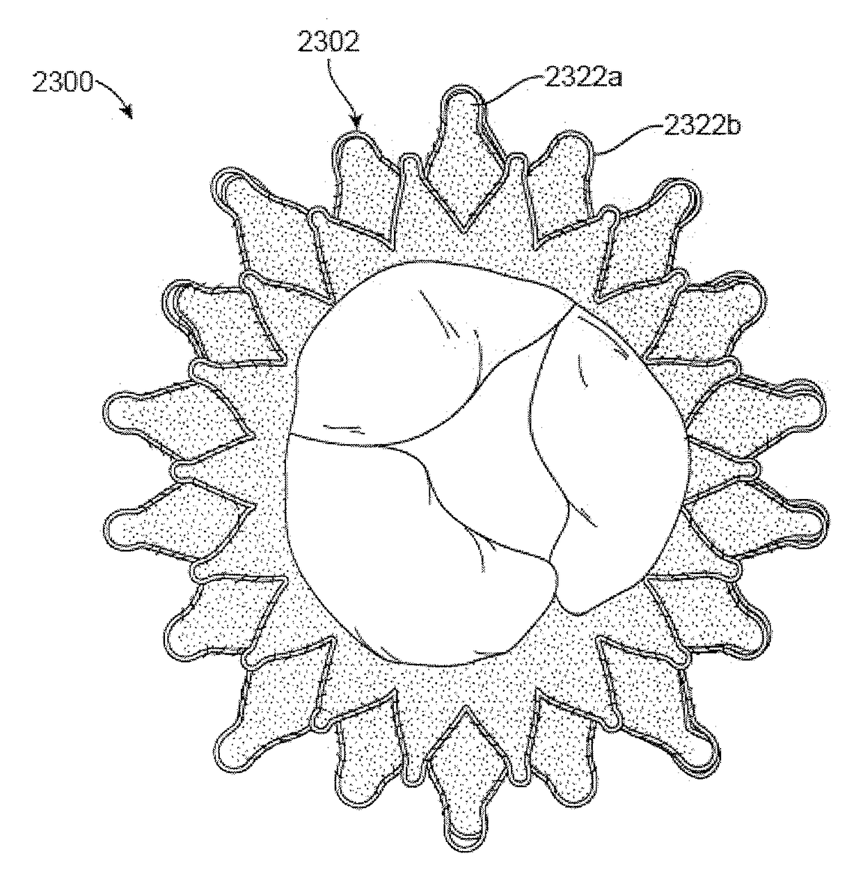
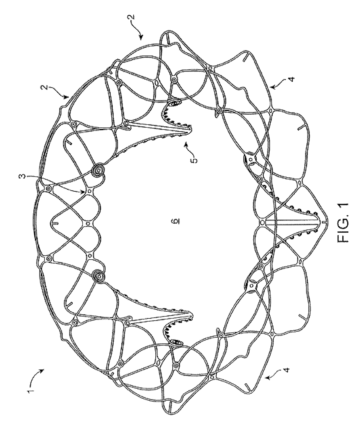
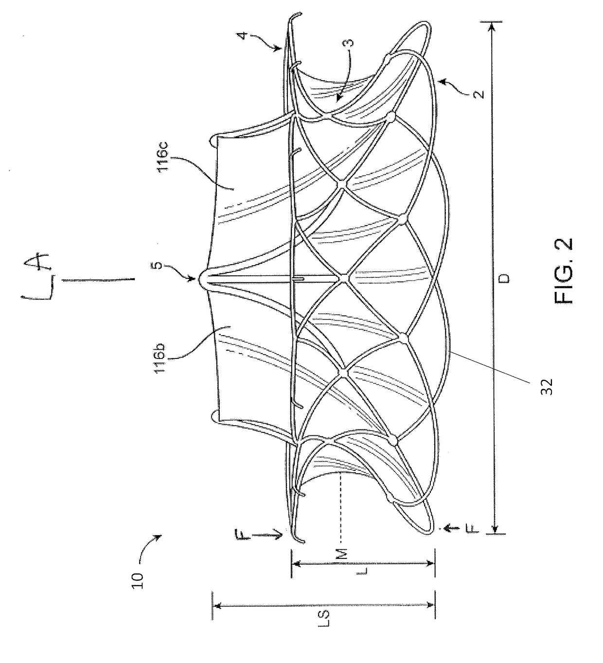
[0067]This disclosure includes replacement heart valves (also referred herein as prosthetic heart valves), methods of manufacturing replacement heart valves, including subassemblies thereof, and methods of using replacement heart valves. This disclosure describes the prostheses in the context of replacement mitral valves, but it is conceivable that the prostheses herein can be used or modified to be used as other replacement heart valves. In some embodiments, the replacement heart valves are self-orienting (at least on one side) replacement mitral valves configured to be delivered using minimally invasive techniques.

[0068]The replacement heart valves herein include an expandable anchor that includes an atrial anchor (e.g., configured to be placed on an atrial side of a mitral valve annulus), a ventricular anchor (e.g., configured to be placed on a ventricular side of a mitral valve annulus), and a central portion axially between the atrial and ventricular anchors. The expandable anc...


PUM


Abstract

A prosthetic mitral valve includes an anchor assembly, an annular strut frame, and a plurality of replacement leaflets secured to the annular strut frame. The anchor assembly includes a ventricular anchor, an atrial anchor, and a central portion therebetween. The annular strut frame is disposed radially within the anchor assembly. An atrial end of the annular strut frame is attached to the anchor assembly such that a ventricular end of the annular strut frame is spaced away from the anchor assembly.

Description

CROSS REFERENCE TO RELATED APPLICATIONS[0001]This application is a continuation of International Patent Application No. PCT / US2016 / 032550, filed May 13, 2016, titled “REPLACEMENT MITRAL VALVES,” now International Publication No. WO 2016 / 183526, which claims priority to U.S. Provisional Application No. 62 / 161,743, titled “REPLACEMENT MITRAL VALVES,” and filed May 14, 2015, and to U.S. Provisional Patent Application No. 62 / 259,565, titled “REPLACEMENT MITRAL VALVES,” and filed Nov. 24, 2015, the entireties of which is incorporated by reference herein.[0002]This application may be related to U.S. patent application Ser. No. 14 / 170,388, filed Jan. 31, 2014, titled “SYSTEM AND METHOD FOR CARDIAC VALVE REPAIR AND REPLACEMENT,” now U.S. Pat. No. 8,870,948, and U.S. patent application Ser. No. 14 / 677,320, filed Apr. 2, 2015, titled “REPLACEMENT CARDIAC VALVES AND METHODS OF USE AND MANUFACTURE,” the entireties of which are incorporated by reference herein.INCORPORATION BY REFERENCE[0003]All...

Claims


Application Information

Patent Timeline
Patent Type & Authority Applications(United States)
IPC IPC(8): A61F2/24
CPCA61F2/2418A61F2/2409A61F2220/0008A61F2230/0071A61F2230/0006A61F2002/825A61F2230/0013A61F2250/0018A61F2250/006A61F2250/0069A61F2230/001A61F2220/0041
Inventor WALLACE, DANNOE, SPENCERGREGG, PETERGRANADA, JUAN F.
Owner CEPHEA VALVE TECH
Why Eureka
Try Eureka