Saw transducer interface to pressure sensing diaphragm

a diaphragm and transducer technology, applied in the field of surface acoustic wave (saw) devices, can solve the problems of unpredictability of performance, difficulty in ensuring the proper mechanical alignment of the diaphragm dimple to its given surface area on the piezoelectric substrate, and inability to meet the requirements of the application, so as to facilitate the mechanical alignment, improve the ease of assembly, and reduce the spring constant

Inactive Publication Date: 2005-05-26
MICHELIN RECH & TECH SA
View PDF7 Cites 31 Cited by
  • Summary
  • Abstract
  • Description
  • Claims
  • Application Information

AI Technical Summary

Benefits of technology

[0011] An advantage of certain embodiments of the present invention is that mechanical alignment is facilitated at the interface formed by the surface indentation of the casing assembly and the projection on the substrate because the alignment now does not need to be as precise during assembly of the casing portions of the sensor assembly. Thus, a SAW sensor with improved ease of assembly is afforded.
[0012] A further advantage of certain embodiments of the present invention is that modification of the sensing diaphragm embodied by the lid portion of the casing assembly is permitted to have a lower spring constant, thus reducing the contribution of hysteresis and nonlinearity from the diaphragm and allowing the piezoelectric substrate to operate closer to its inherent capability for linearity and stability.

Problems solved by technology

Proper mechanical alignment of the diaphragm dimple to its given surface area on the piezoelectric substrate can sometimes be difficult to ensure due to the nature of positioning a relatively small dimple point to a precise location on the substrate.
Additional uncertainty may arise when aligning such portions of a SAW device due to potential unpredictability in the performance of the casing assembly during assembly and welding.
While various implementations of acoustic wave devices such as SAW sensors have been developed, no design has emerged that generally encompasses all the desired characteristics as hereafter presented in accordance with the subject technology.

Method used


Image

  • Saw transducer interface to pressure sensing diaphragm
  • Saw transducer interface to pressure sensing diaphragm
  • Saw transducer interface to pressure sensing diaphragm

Examples


Embodiment Construction

[0022] As discussed in the Summary of the Invention section, the present subject matter is particularly concerned with surface acoustic wave (SAW) devices utilized for sensing physical parameters, such as pressure and / or temperature, as may be associated with a tire or wheel environment. More particularly, an improved interface between respective pressure-sensing diaphragm and internal sensor components of such SAW devices is provided.

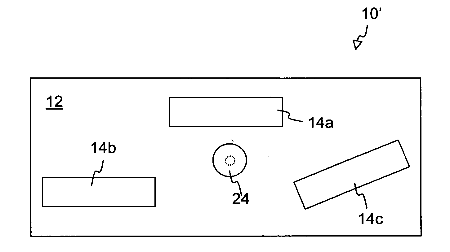
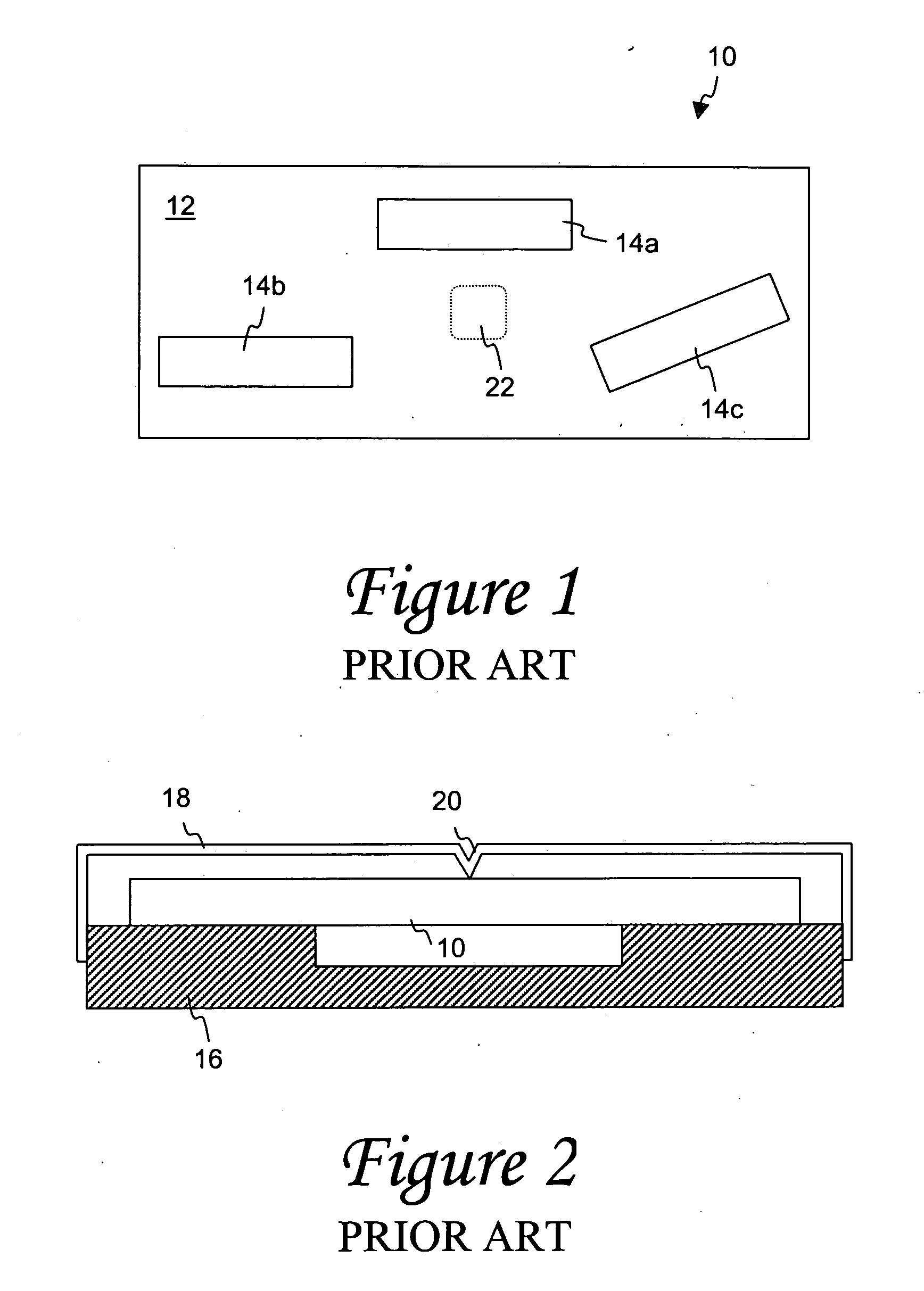
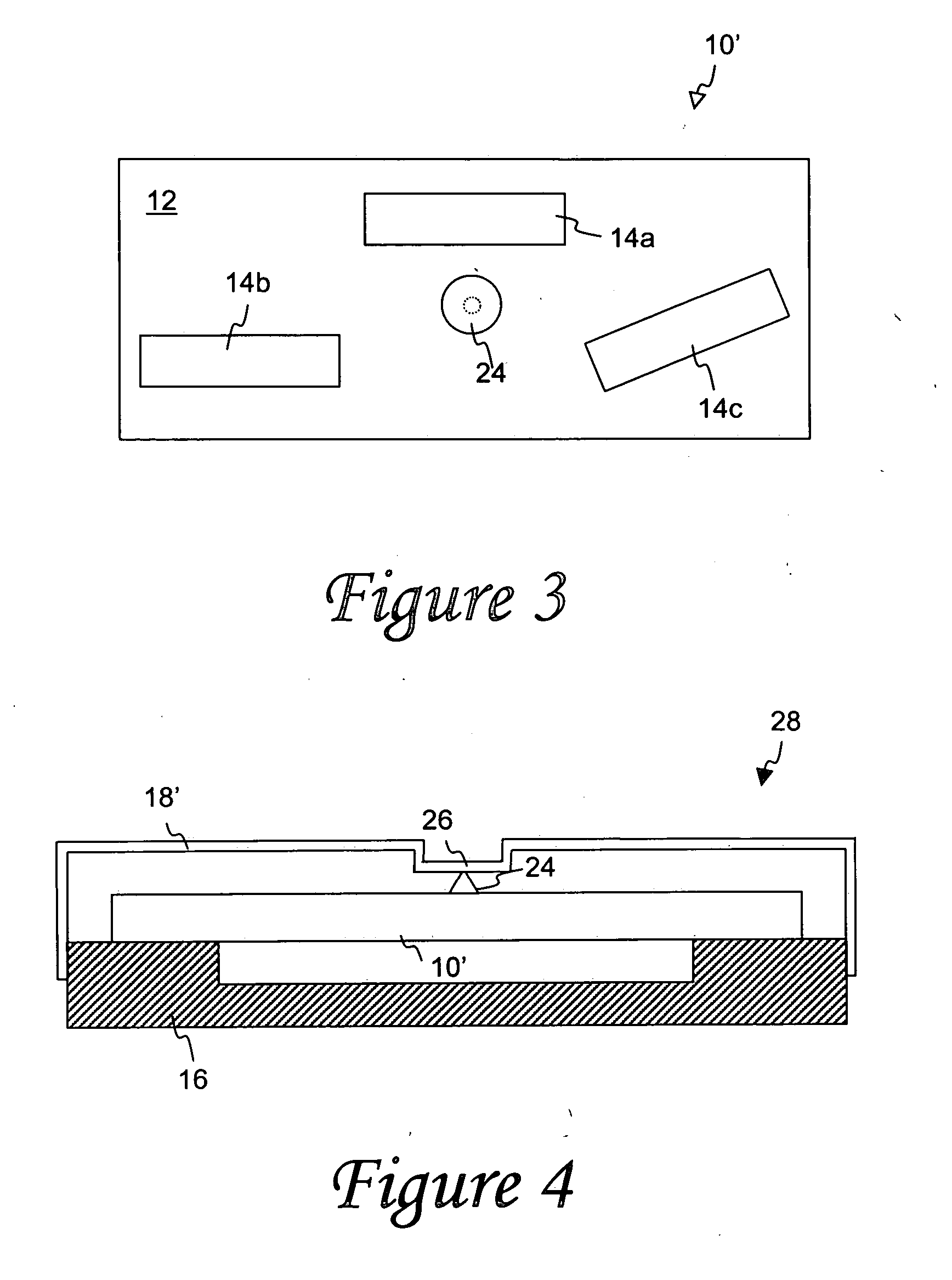
[0023]FIGS. 1 and 2 present aspects of a prior art SAW device, including general casing features and a specific exemplary interface between pressure-sensing diaphragm and internal sensor components of such a SAW device. FIGS. 3 and 4 illustrate an exemplary SAW device in accordance with the present invention, with improved casing features and interface between pressure-sensing components of such SAW device. The exemplary SAW device of FIGS. 3 and 4 may be incorporated in a tire or wheel assembly to measure various physical parameters associated with s...


PUM

PropertyMeasurementUnit
areaaaaaaaaaaa
resonant frequenciesaaaaaaaaaa

Abstract

A sensor assembly for monitoring physical parameters in a given environment, such as in a tire or wheel assembly, includes an improved interface between sensor components. The sensor assembly includes a piezoelectric substrate on which resonator elements, such as surface acoustic wave (SAW) resonators are provided. The resonators are configured to produce electrical output at predetermined resonator frequency ranges that can be monitored to determined such information as pressure and temperature to which such devices are subjected. A projection is formed on a surface of the piezoelectric substrate, which selectively interfaces with a recessed surface area in a flexible lid casing component. The lid casing component and a rigid base casing component combine to form an enclosed package for the sensor assembly. An antenna may be coupled to the sensor assembly to facilitate receipt and / or transmission of communicated signals.

Description

FIELD OF THE INVENTION [0001] The present invention generally concerns surface acoustic wave (SAW) devices utilized for sensing physical parameters, such as pressure and / or temperature, as may be associated with a tire or wheel environment. More particularly, an improved interface between respective pressure-sensing diaphragm and internal sensor components of such SAW devices is provided. BACKGROUND OF THE INVENTION [0002] The incorporation of electronic devices with pneumatic tire structures yields many practical advantages. Tire electronics may include sensors and other components for obtaining information regarding various physical parameters of a tire, such as temperature, pressure, number of tire revolutions, vehicle speed, etc. Such performance information may become useful in tire monitoring and warning systems, and may even potentially be employed with feedback systems to regulate proper tire pressure levels. [0003] One particular type of condition-responsive device that has...

Claims


Application Information

Patent Timeline
Patent Type & Authority Applications(United States)
IPC IPC(8): B60C23/04B60C23/20G01L9/00G01L17/00
CPCG01L9/0025B60C23/0408
Inventor SINNETT, JAY CLIFFORD
Owner MICHELIN RECH & TECH SA
Why Eureka
Try Eureka