Vibration damping device

a technology of vibration damping and spring constant, which is applied in the direction of shock absorbers, machine supports, mechanical equipment, etc., can solve the problems of poor use durability, difficult to increase the spring constant, and remarkably difficult to regulate the great oscillatory motion in the front and rear directions of the vehicle in a large-size power plant, etc., to achieve easy shear deformation, easy to tune the spring constant, and the effect of spring constan

Inactive Publication Date: 2007-10-04
SUMITOMO RIKO CO LTD
View PDF4 Cites 7 Cited by
  • Summary
  • Abstract
  • Description
  • Claims
  • Application Information

AI Technical Summary

Benefits of technology

[0015]According to different one of preferable modes of the present invention, a stopper is further provided on a portion of the outer fitting corresponding to the inner fitting to regulate a relatively excessive displacement in the horizontal direction of the inner fitting.
[0016]Accordingly, in the vibration damping device in accordance with the present invention, since the inner fitting and the outer fitting are connected to each other by the substantially T-shaped rubber elastic body made up of the paired rubber arm portions and the rubber leg portion, the device is subjected to compressive deformation action by loads applied in two orthogonal directions, the horizontal direction and the vertical direction, based on the T shape of the rubber elastic body. Therefore, the spring constants in these two directions can be increased effectively at the same time. Moreover, since the rubber arm portion, which is the head portion of the T-shaped rubber elastic body, is formed so that the thickness thereof decreases gradually from the inner fitting side toward the outer fitting side, the paired rubber arm portions are easily shear deformed by a load applied in the vertical direction, no great influence is exerted on the spring constant in the vertical direction that is regulated by the rubber leg portion, which is the leg portion of the T shape, and the tuning of the spring constant is made easy. Also, regarding the load applied in the horizontal direction, since the paired rubber arm portions are easy to deform in the connection side portion with the outer fitting, in which the thickness is decreased, stresses are distributed and uniformed, by which the occurrence of defects such as cracks and fractures is restrained or prevented effectively, and the durability of the paired rubber arm portions can be improved advantageously.
[0017]Also, in the vibration damping device in accordance with the present invention, the rubber leg portion of the rubber elastic body, subjected to the vertical load, is formed so that each of both side surfaces of the rubber leg portion is formed by an inwardly depressed curved surface, and is formed into a curved broaden shape toward the outer fitting side. Therefore, even if a high load acts and the rubber leg portion is compressedly deformed, the buckling of the rubber leg portion can be prevented effectively. Moreover, since both side surfaces are not formed by linear flat surfaces but formed by inwardly curved surfaces, the free length is long. Thereby, the applied stresses are distributed and uniformed, and hence the side surface of the rubber leg portion is deformed easily. Therefore, effective improvement in the durability can be achieved advantageously.
[0018]Thereupon, in the vibration damping device according to the present invention, while the spring constants of the rubber elastic body in the two orthogonal directions, the vertical direction and the horizontal direction, are increased, at the same time, the spring constant ratio of the rubber elastic body can be tuned easily, and also the occurrence of defects in the rubber elastic body is prevented or restrained, by which the durability can be increased advantageously.

Problems solved by technology

However, in the horizontal direction, which is the front and rear direction of the vehicle, the inverse V-shaped rubber elastic body supports an applied load by means of shear deformation, so that it is difficult to increase the spring constant.
Therefore, it is remarkably difficult to regulate great oscillatory motion in the front and rear direction of the vehicle in a large-size power plant (engine).
Therefore, this engine mount has a problem that the usage durability thereof is poor.
Therefore, in this construction, a crack and a fracture etc. are liable to be generated, which causes a problem of deteriorating the durability of rubber elastic body.
In addition, it is difficult to sufficiently absorb the deformation of the rubber leg portion.
Therefore, this construction has a problem of generating a crack and a fracture etc., and thereby the durability of the rubber leg portion is deteriorated.

Method used


Image

  • Vibration damping device
  • Vibration damping device
  • Vibration damping device

Examples


Embodiment Construction

[0024]To clarify the present invention further specifically, an embodiment of the present invention will now be described with reference to the accompanying drawings.

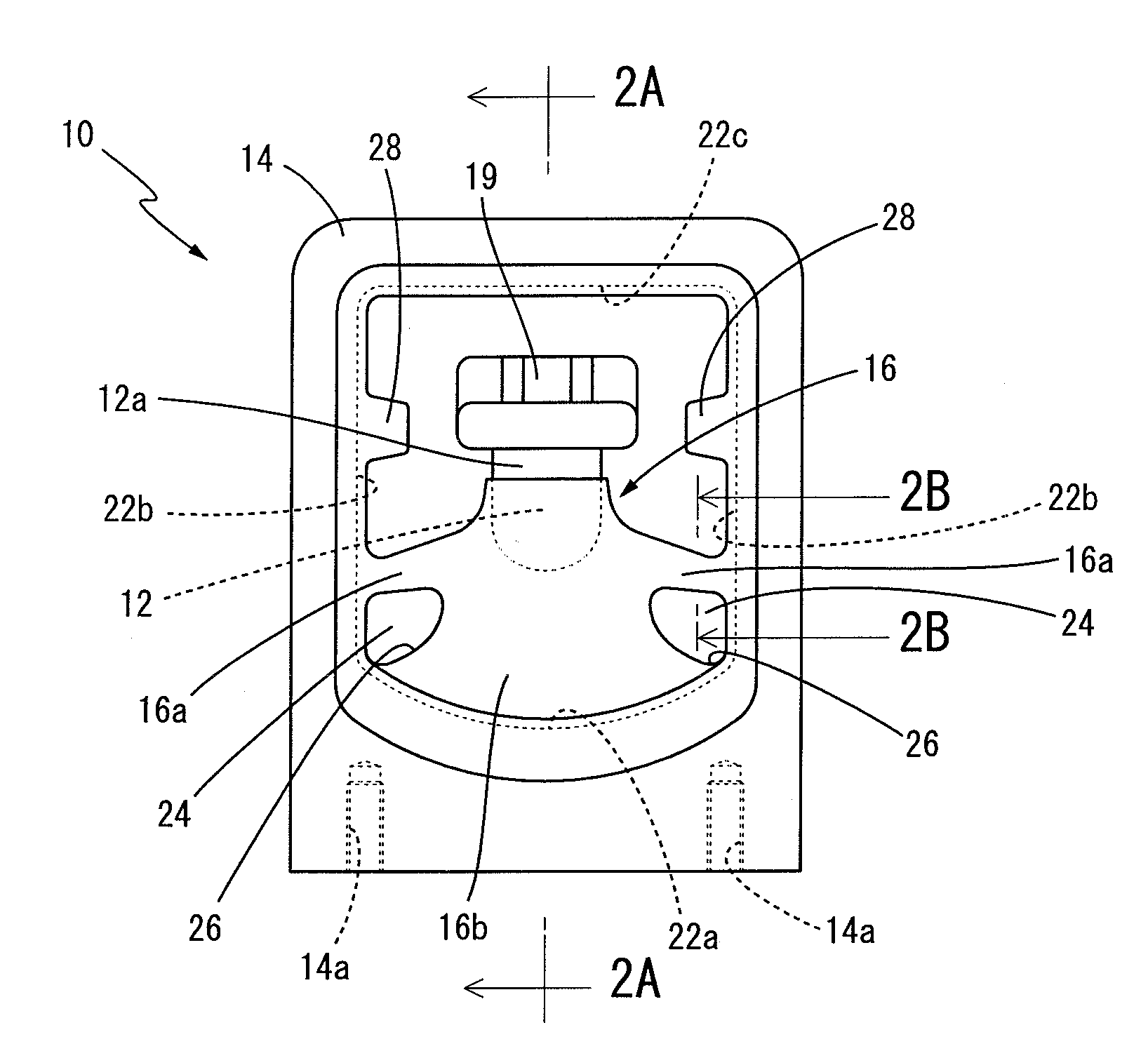
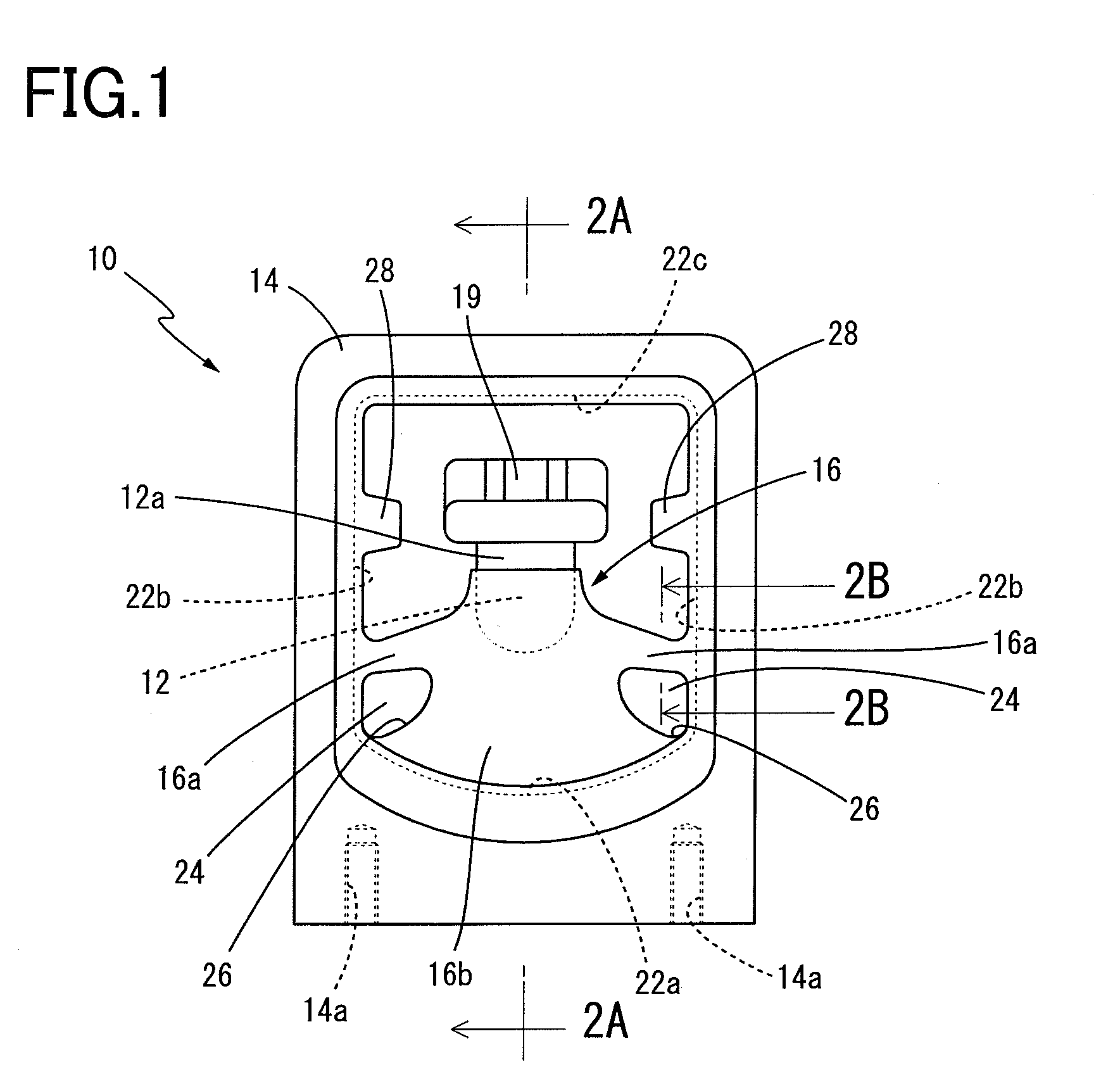
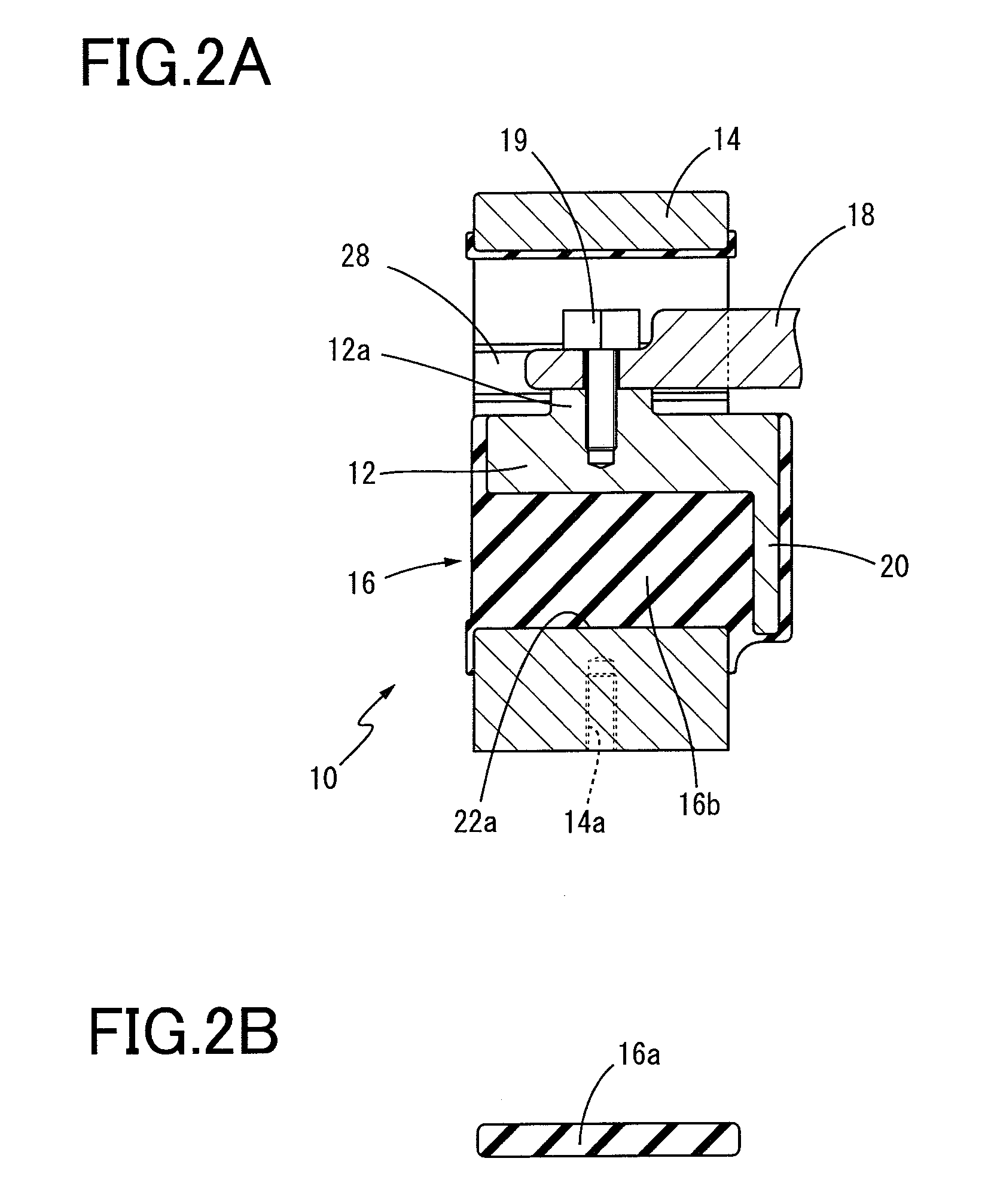
[0025]FIGS. 1 to 3 show an engine mount 10, which is one embodiment of a vibration damping device in accordance with the present invention. In FIG. 1, the engine mount 10 has a semi-columnar inside element 12 extending in the axial direction perpendicular to the drawing sheet surface of FIG. 1, as an inner fitting, and also has an outer cylindrical element 14 having a rectangular cylindrical shape formed by combining a rectangle and an arcuate shape, in which the inside element 12 is located in the inside space, as an outer fitting separately located on the outside of the inside element 12. Further, the inside element 12 and the outer cylindrical element 14 are connected by a rubber elastic body 16, having approximately T-shape in the cross section perpendicular to the axial direction, so that the inside element 12 is s...


PUM


Abstract

There is provided a vibration damping device including; a pair of rubber arm portions connecting an inner fitting and an outer fitting to each other in the horizontal direction; and a rubber leg portion connecting in the vertical direction; the paired rubber arm portions are formed so that the thickness thereof decreases gradually from the inner fitting side toward the outer fitting side, and the rubber leg portion is formed so that each of both side surfaces is formed by an inwardly depressed curved surface, and is formed into a curved broaden shape toward the outer fitting side. Thereby, a spring constant in the horizontal direction is increased advantageously while a spring constant in the vertical direction kept large, and the durability of the rubber elastic body can be increased effectively.

Description

[0001]The present application is based on Japanese Patent Application No. 2006-092875 filed on Mar. 30, 2006, the contents of which are incorporated herein by reference.BACKGROUND OF THE INVENTION[0002]1. Field of the Invention[0003]The present invention relates to a vibration damping device. More particularly, it relates to an improvement structure of a vibration damping device which is suitably used as an engine mount, in which an inner fitting and an outer fitting disposed separately on the outside of the inner fitting are connected to each other by a rubber elastic body substantially having a T shape as a whole.[0004]2. Description of the Related Art[0005]As a vibration damping connector or a vibration damping support interposed between members constituting a vibration transmission system, a vibration damping device having a construction such that an inner fitting attached to one member and an outer fitting attached to the other member, which is arranged separately on the outsid...

Claims


Application Information

Patent Timeline
Patent Type & Authority Applications(United States)
IPC IPC(8): F16F13/16
CPCF16F1/52F16F1/3615
Inventor OKANAKA, TAKEHIROMAEDA, KOUICHIMATSUOKA, TSUTOMU
Owner SUMITOMO RIKO CO LTD
Why Eureka
Try Eureka