
Component assembly system and method using inspection information

Active Publication Date: 2017-11-16
FANUC LTD
View PDF1 Cites 5 Cited by
  • Summary
  • Abstract
  • Description
  • Claims
  • Application Information

AI Technical Summary

Benefits of technology

The patent text describes a method for determining which components should be combined together in a product assembly. The method takes into account the ease of assembly and the dimensional accuracy of the components. By organizing the components based on their ease of assembly and dimensional accuracy, the method minimizes the dispersion of these properties between different combinations of components. This results in a more stable and reliable product assembly.

Problems solved by technology

In assembling components, a dimensional error of each component has an effect on the difficulty in assembling the components or on the quality of an assembled product.
In particular, when two components, which are difficult to assemble due to dimensional errors thereof, are selected as the components to be assembled, the operation of the automatic assembly equipment may be suspended.
Further, the assembling of the components may be impossible due to an error which is unexpected when designing the equipment.
Therefore, it may be difficult to improve the quality (or dimensional accuracy) of the product.
In this technique, however, some of the first components which do not form the optimum clearance relative to the second component may be stocked for a long time.
Therefore, when a plurality of groups of components is provided, it may be difficult to determine an optimum combination of the components between the groups.

Method used


Image

  • Component assembly system and method using inspection information
  • Component assembly system and method using inspection information
  • Component assembly system and method using inspection information

Examples


Embodiment Construction

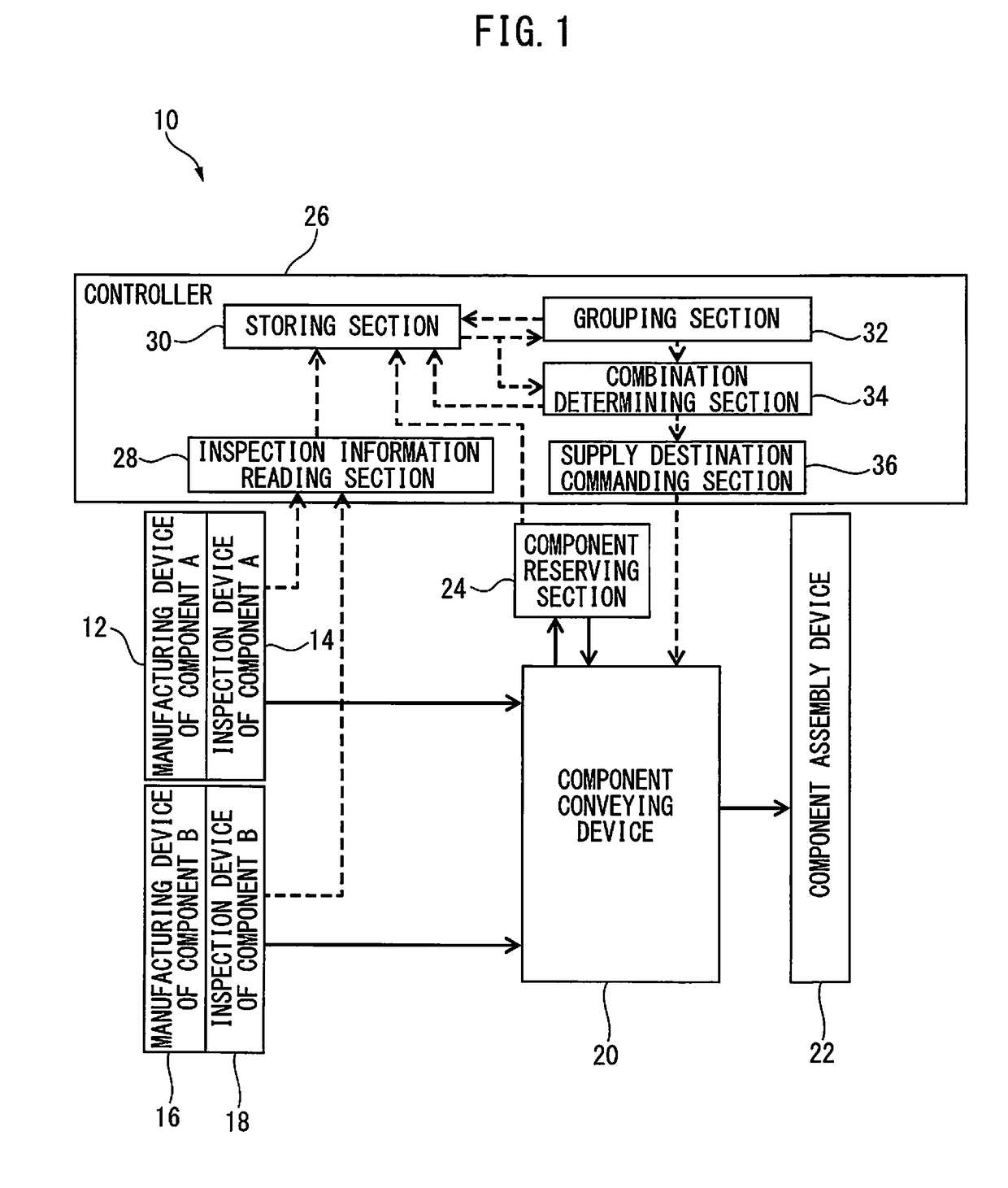
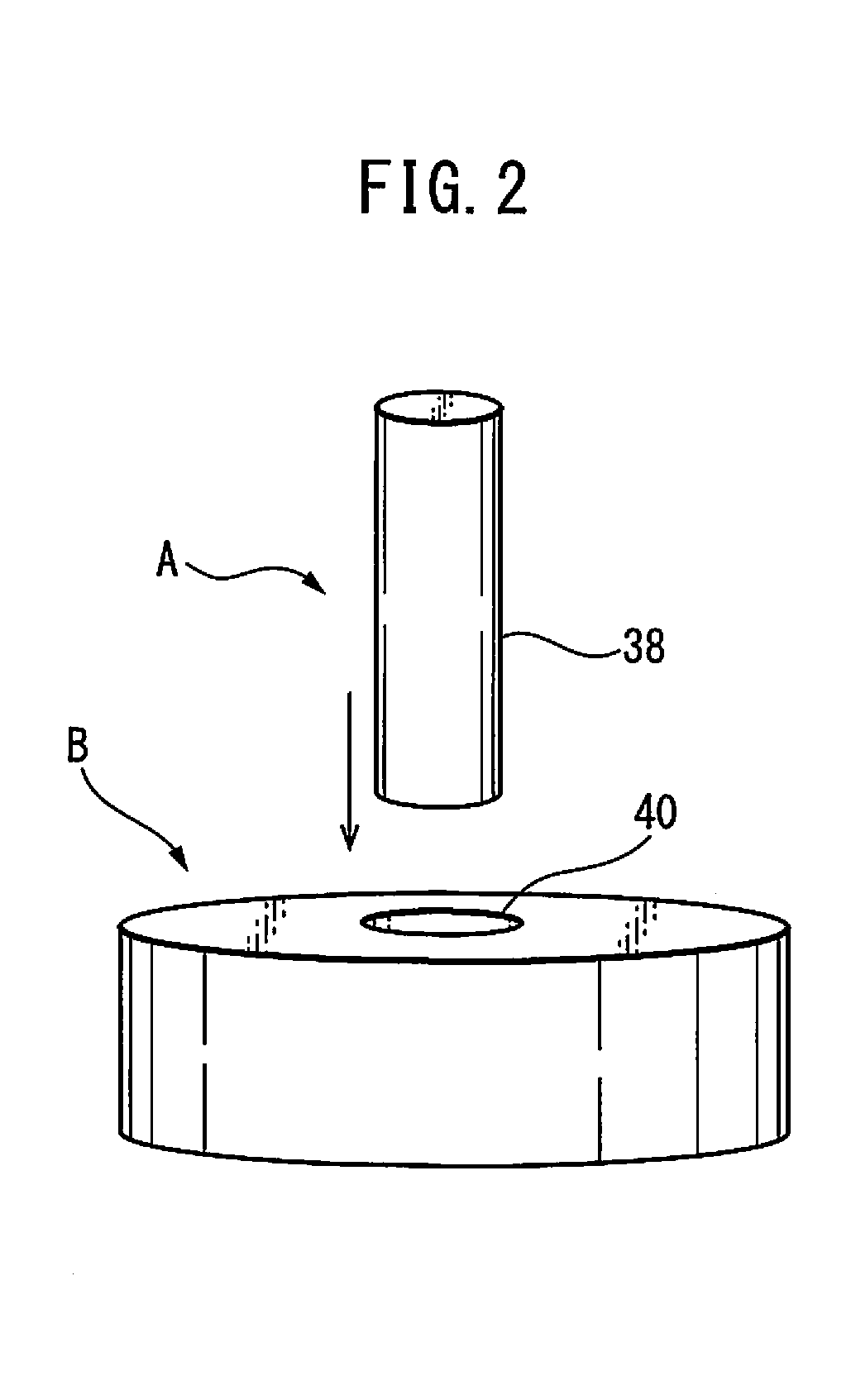
[0024]FIG. 1 is a functional block diagram of a component assembly system 10 according to a preferred embodiment of the present invention. Component assembly system 10 includes: a first manufacturing device 12 such as a machine tool for manufacturing a first component A; a first inspection device 14 for inspecting (e.g., measuring a dimension of) component A manufactured by first manufacturing device 12; a second manufacturing device 16 such as a machine tool for manufacturing a second component B configured to be assembled to component A; a second inspection device 18 for inspecting (e.g., measuring a dimension of) component B manufactured by second manufacturing device 16; a component conveying device 20 such as a robot or a belt conveyor configured to convey component A inspected by first inspection device 14 and component B inspected by second inspection device 18; and a component assembly device 22 configured to assemble components A and B conveyed by component conveying device...


PUM


Abstract

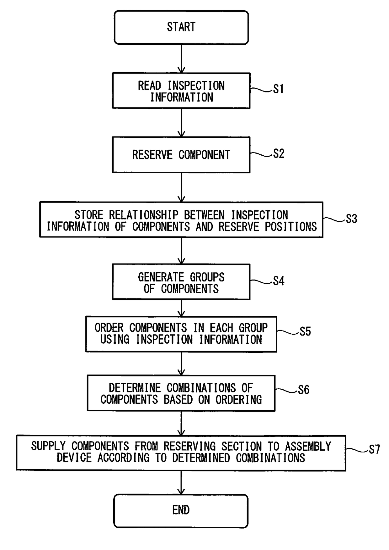
A component assembly system and method, by which an optimum combination of components can be determined by using inspection information of each component. The system has: an inspection information reading section for reading first and second inspection information regarding assembling of first and second components; a component reserving section for reserving each component; a storing section for storing a relationship between the inspection information of each component and a reserve position of each component; a grouping section for providing at least one first and second groups respectively including the first and second components; a combination determining section for determining a combination of the first and second components on one-to-one correspondence, by using the first and second inspection information; and a component conveying device for conveying the first and second components corresponding to the determined combination from the component reserving section to an assembly device, by using the stored relationship.

Description

BACKGROUND OF THE INVENTION1. Field of the Invention[0001]The preset invention relates to a component assembly system and a component assembly method, for assembling a plurality of components.2. Description of the Related Art[0002]There are various well-known systems or methods for manufacturing a product by assembling a plurality of components. As a relevant prior art document, JP H09-314431 A discloses an automatic assembly / convey system for measuring, selecting, assembling and conveying two components configured to be fitted with each other, such as a valve adjuster and a body of a plunger.[0003]Further, JP 2009-059220 A discloses a production management system used in a production method by which a plurality of components each having a fitting or fitted portion are manufactured, and then the fitting portion and the fitted portion of the manufactured components are assembled to each other so as to make a product.[0004]In assembling components, a dimensional error of each componen...

Claims


Application Information

Patent Timeline
IPC IPC(8): G06F17/30G06F7/16B07C5/34G01N21/88
CPCG06F17/30997G06F17/30988G06F17/30973G06F17/30985G06F7/16G01N21/88B07C5/34G01N2201/024B23P21/00G05B19/41805G06Q50/04Y02P90/30G06F16/907G06F16/90328G06F16/90344G06F16/90348
Inventor MORIMOTO, KENJIROU
Owner FANUC LTD
Learn More