
Color night vision system and operation method thereof

a color night vision and operation method technology, applied in the field of color night vision system and an operation method of the color night vision system, can solve the problems of providing a relatively low image resolution, not being able to properly operate in hot weather conditions, and relatively short visibility, so as to prevent the noise of an rgb image

Inactive Publication Date: 2017-11-16
CENT FOR INTEGRATED SMART SENSORS FOUND
View PDF7 Cites 26 Cited by
  • Summary
  • Abstract
  • Description
  • Claims
  • Application Information

AI Technical Summary

Benefits of technology

This patent describes a color night vision system that can prevent a difference in perspective between a red, green, blue (RGB) image and an infrared (IR) image. This is achieved by using a single-4-color image sensor to process both RGB and IR light signals. Additionally, the system can reduce noise in the RGB image and decide on a denoising level and a synthesis ratio between the RGB and IR images based on the sensor. This results in a more accurate and reliable image for viewing in low-light environments.

Problems solved by technology

The passive system may secure a field of view up to about 300 m ahead without using a separate illumination device, however, has a relatively large sensor size, provides a relatively low image resolution, and does not properly operate in a hot weather condition.
On the other hand, the active system provides the relatively short visibility of 150 to 200 m compared to the passive system and does not provide an excellent image when it is foggy or rainy, however, has a relatively small sensor size and acquires a relatively high resolution image.
However, such color night vision systems need to use an expensive large-diameter lens.
Accordingly, when the color image and the IR image are synthesized in this situation, that is, when the color image and the IR image are synthesized without performing a separate denoising, an acquired image includes relatively large noise.

Method used


Image

  • Color night vision system and operation method thereof
  • Color night vision system and operation method thereof
  • Color night vision system and operation method thereof

Examples


Embodiment Construction

[0039]Hereinafter, some example embodiments will be described in detail with reference to the accompanying drawings. Regarding the reference numerals assigned to the elements in the drawings, it should be noted that the same elements will be designated by the same reference numerals, wherever possible, even though they are shown in different drawings. Also, in the description of embodiments, detailed description of well-known related structures or functions will be omitted when it is deemed that such description will cause ambiguous interpretation of the present disclosure.

[0040]Also, terminologies used herein refer to terms used to appropriately represent the example embodiments and may vary based on a reader, the intent of an operator, or custom of a field to which this disclosure belongs, and the like. Accordingly, the definition of the terms should be made based on the overall description of the present specification.

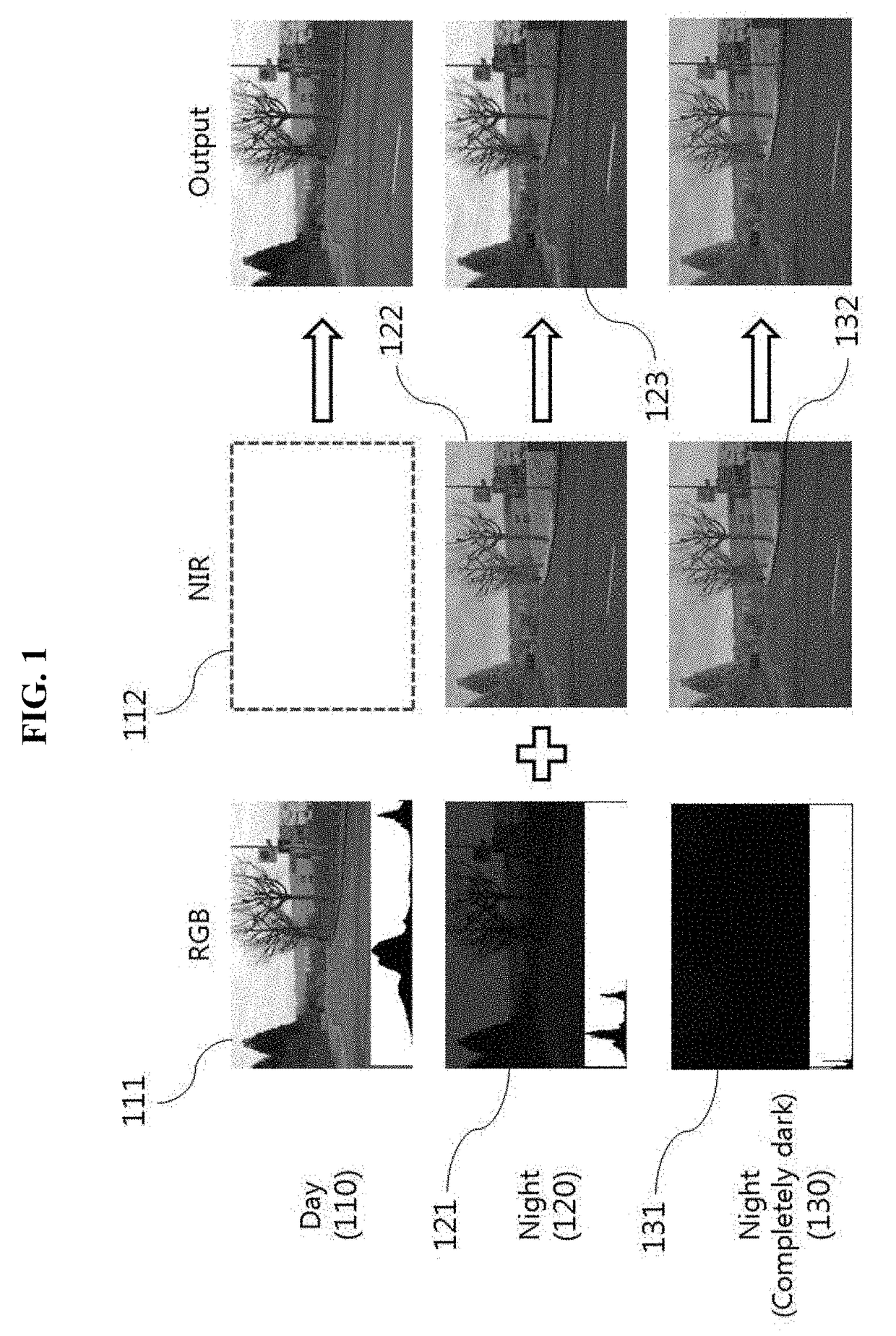
[0041]FIG. 1 illustrates an example of describing an operation...


PUM


Abstract

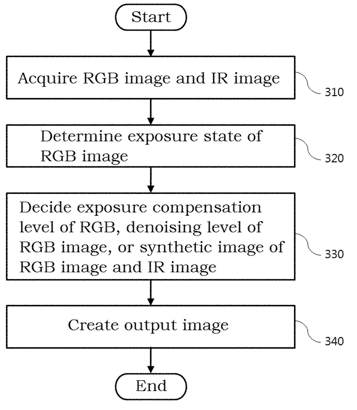
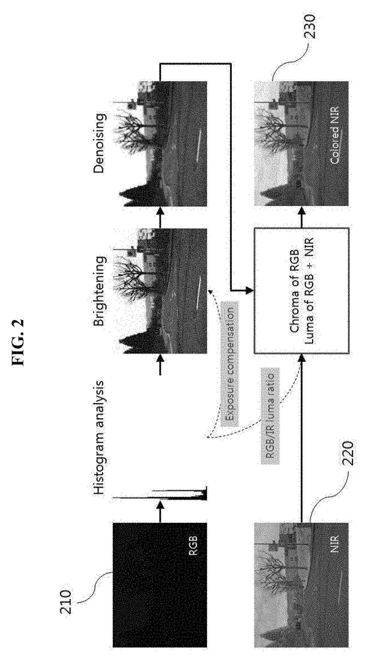
Disclosed is a color night vision system including a single-4-color image sensor configured to acquire a red, green, blue (RGB) image and an infrared (IR) image by processing RGB light signals and an IR light signal for each wavelength; and a processor configured to determine an exposure state of the RGB image by analyzing a brightness distribution of the RGB image, to decide at least one of an exposure compensation level of the RGB image, a denoising level of the RGB image, or a synthesis ratio between the RGB image and the IR image based on the determination result, and to create an output image based on the decision result that is made using the RGB image and the IR image.

Description

CROSS-REFERENCE TO RELATED APPLICATION[0001]This application claims the priority benefit of Korean Patent Application No. 10-2016-0057605, filed on May 11, 2016, in the Korean Intellectual Property Office, the disclosure of which is incorporated herein by reference.BACKGROUND1. Field of the Invention[0002]The following example embodiments relate to a color night vision system and an operation method of the color night vision system, and more particularly, to technology using a red, green, blue (RGB) image and an infrared (IR) image to acquire an identifiable image in a low luminance environment.2. Description of the Related Art[0003]A night vision is generally used to acquire an identifiable image in a low luminance environment in an automotive night vision system helping drive at night and in a surveillance camera system.[0004]An automotive night vision system is classified into a passive system which acquires an image using a thermal imaging camera without using a separate illumin...

Claims


Application Information

Patent Timeline
IPC IPC(8): G06K9/46H04N5/33G06T5/00G06T5/40H04N7/18G06T11/60
CPCG06T2207/10024G06T2207/10048G06K9/4661H04N5/332G06K9/4652G06T11/60H04N7/183G06T5/002G06T5/009G06T5/40G06T5/50G06T2207/20221G06T11/001H04N23/11G06T5/92G06T5/70H04N25/131H04N5/265H04N23/45H04N23/741G06T5/90
Inventor PARK, KI YEONGKIM
Owner CENT FOR INTEGRATED SMART SENSORS FOUND
Learn More