Wire with terminal and manufacturing method therefor

Active Publication Date: 2017-11-16
AUTONETWORKS TECH LTD +3
View PDF10 Cites 4 Cited by
  • Summary
  • Abstract
  • Description
  • Claims
  • Application Information

AI Technical Summary

Benefits of technology

[0031]In addition, according to the present technology, in the state where the first compression ratio is set between 85% and 95% inclusive, so that the strand wires are electrically connected, the crimp portion is crimped on the core wire with the second compression ratio set lower than the first compression ratio. Thus, the core wire is reliably compressed by the crimp portion, whereby the electrical connection between the crimp portion and the core wire

Problems solved by technology

However, it has been discovered that, even when ultrasonic vibrations are applied to the core wire prior to crimping the terminal onto the core wire, as in Patent Document 1, the electrical resistance between the electric wire and the terminal may not be sufficiently decreased.
In this case, while the electrical resistance can be decreased by compressing the core wire more during the crimping, excessive compression of the core wire may cause severing of the strand wires constituting the core wire.
If the first compression ratio is made greater than 95% for low compression of the core wire, the surfaces of the strand wires may not be sufficiently roughened, and the electrical resistance between the plurality of strand wires may fail to be sufficiently decre

Method used


Image

  • Wire with terminal and manufacturing method therefor
  • Wire with terminal and manufacturing method therefor
  • Wire with terminal and manufacturing method therefor

Examples


second embodiment

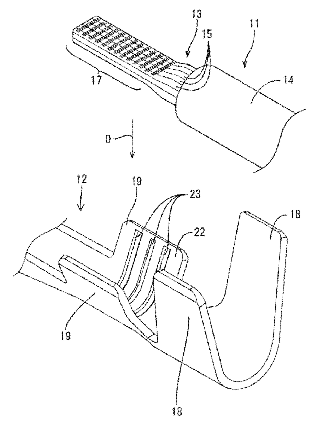
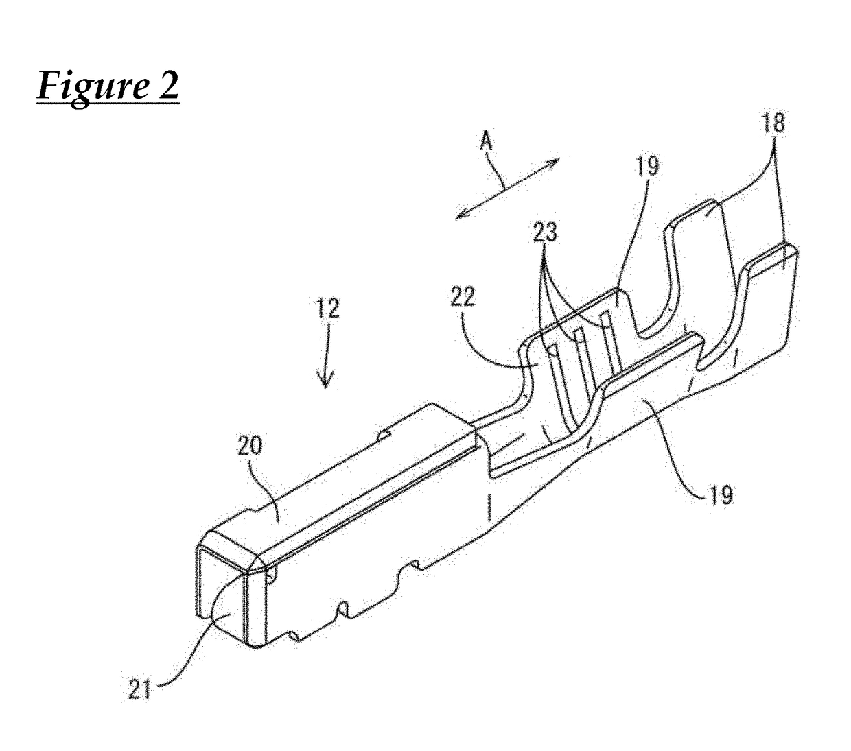
[0167]A terminal-attached electric wire 32 according to a second embodiment of the present design will now be described with reference to FIG. 21. The terminal according to the present embodiment is a so-called splice terminal 30 (an example of the terminal) which does not include the connection portion 20. As illustrated in FIG. 21, the splice terminal 30 is configured such that, when two core wires 13 of the electric wires 11 are connected, the insulation coating 14 is peeled at the end of one of the electric wires 11 to expose the core wire 13. With respect to the other electric wire 11, the insulation coating 14 is peeled at the intermediate portion to expose the core wire 13. Each of the exposed two core wires 13 is crimped by one of a pair of wire barrels (an example of the crimp portion) 31.

[0168]In the present embodiment, in the state where the two core wires 13 of the electric wires 11 are crimped by the wire barrels 31, 20 or more strand wires 15 are crimped on the wire ba...

third embodiment

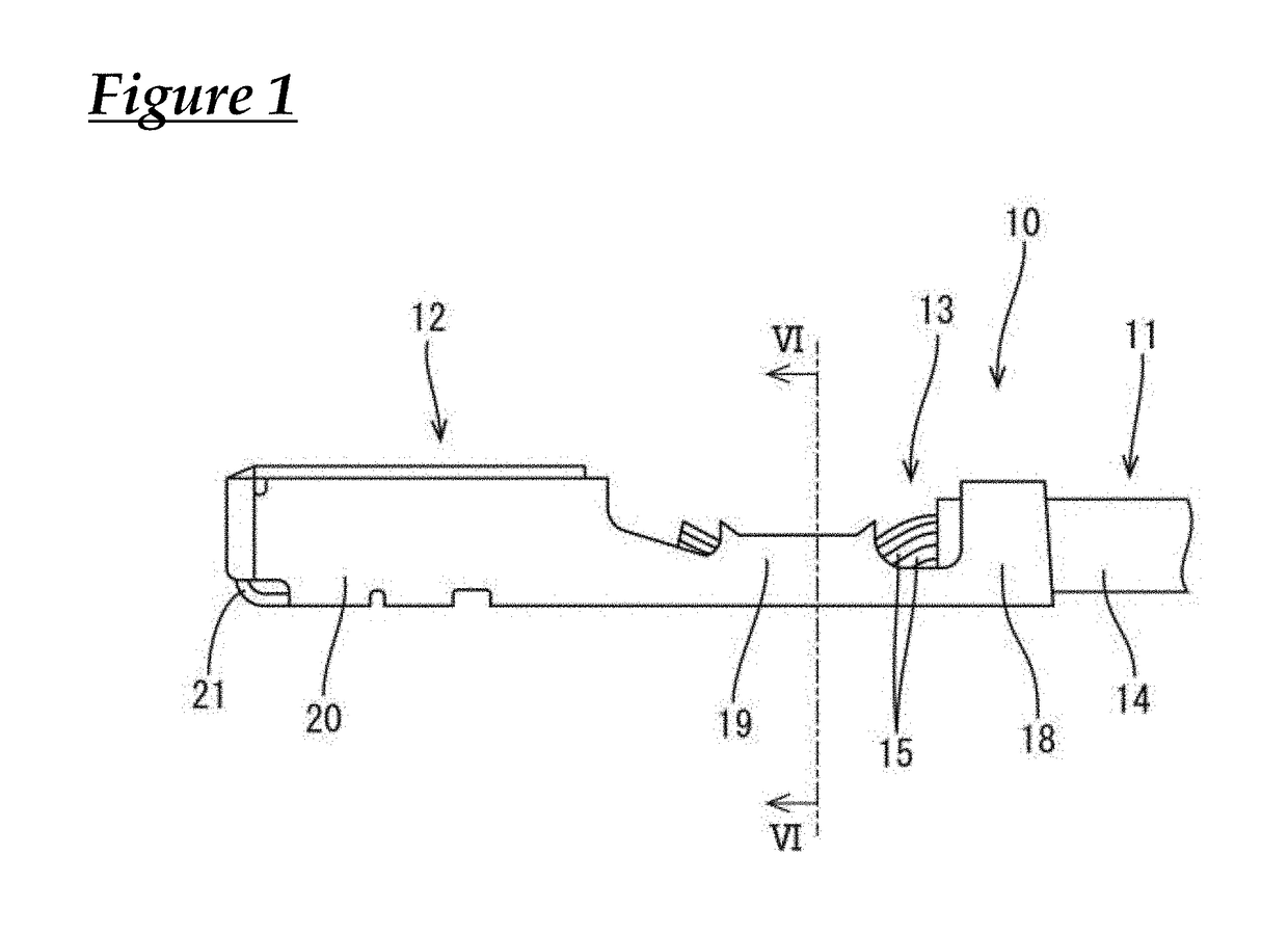
[0169]A terminal-attached electric wire 53 according to a third embodiment of the present design will be described with reference to FIG. 22. From the end of the electric wire 11, the insulation coating 14 is peeled only by a predetermined length, whereby the core wire 13 is exposed from the tip-end portion of the insulation coating 14. On the outer periphery of the core wire 13, the wire barrels 19 are crimped.

[0170]In the core wire 13, a primary compressed region 50 is formed in which the core wire 13 is compressed by, for example, pinching the core wire 13 with a pair of jigs and applying ultrasonic vibrations to the core wire 13.

[0171]As illustrated in FIG. 22, the wire barrels 19 are crimped in a region including the primary compressed region 50. Of the core wire 13, a region of the primary compressed region 50 that has been compressed by the application of ultrasonic vibrations which has further been compressed by the wire barrels 19 provides a secondary compressed region 51. ...


PUM


Abstract

A method for manufacturing a terminal-attached electric wire including an electric wire including a core wire having plurality of strand wires, and a female terminal including wire barrels crimped around the core wire. The method includes a first step of applying ultrasonic vibrations to the core wire, and a second step of crimping the wire barrels in a region of the core wire to which ultrasonic vibrations have been applied. The first step includes applying ultrasonic vibrations to the core wire while leaving a compression margin for the crimping by the second step such that the resistance between the electric wire and the female terminal is stabilized until the strand wires of the terminal-attached electric wire are severed when the core wire of the terminal-attached electric wire is further compressed after the second step.

Description

CROSS REFERENCE TO RELATED APPLICATIONS[0001]This application claims the priority of Japanese patent application JP2014-253135 filed on Dec. 15, 2014, the entire contents of which are incorporated herein.TECHNICAL FIELD[0002]The present invention relates to a terminal-attached electric wire, and a method for manufacturing a terminal-attached electric wire.BACKGROUND ART[0003]Conventionally, as a terminal-attached electric wire, the electric wire described in Patent Document 1 (JP2011-82127) is known, for example. The electric wire includes an electric wire including a core wire having a plurality of strand wires, with a terminal crimped onto the core wire exposed from the electric wire. The terminal includes a crimp portion which is crimped so as to wrap around the outside of the core wire. Since the crimp portion is crimped so as to wrap around the outside of the core wire, the electric wire and the terminal are electrically connected. In the manufacturing of the terminal-attached ...

Claims


Application Information

Patent Timeline
IPC IPC(8): H01R43/02H01R11/11H01R4/18H01R4/62H01R43/05H01R43/048
CPCH01R43/0207H01R43/05H01R43/048H01R11/11H01R4/18H01R4/625H01R4/185H01R4/62H01R43/28
Inventor OOTSUKA, TAKUJIHIRAI, HIROKIONO, JUNICHIMIYAMOTO, KENJIOOTA, TOSHIYANAKASHIMA, TAKAHITOKOBAYASHI, HIROSHI
Owner AUTONETWORKS TECH LTD
Why Eureka
Try Eureka