
Test element analysis system

Active Publication Date: 2019-01-03
ROCHE DIAGNOSTICS OPERATIONS
View PDF0 Cites 0 Cited by
  • Summary
  • Abstract
  • Description
  • Claims
  • Application Information

AI Technical Summary

Benefits of technology

The patent ensures that the contact surfaces of a evaluation device's contact element and a test element are always reliably and definedly connected, even after many contact operations and under high mechanical strain. This improves the reliability and durability of the electrical connection between the two components.

Problems solved by technology

Since the contact surfaces should, on the one hand, ensure that the transfer of electrical current is as optimal as possible which requires a certain contact pressure, but, on the other hand, joining the contact connection and in particular repeated joining and separating the contact connection puts a great strain on the connection, the contact surfaces of the evaluation instruments are often provided with a layer of noble metal for example by plating or galvanizing with gold, silver, platinum or palladium.
The often high mechanical strain on the contact surfaces especially due to abrasion, deposition or scratching of the contact surfaces is thus also a problem because a certain contact pressure has to be ensured for a reliable electrical contact and a certain insertion path of the test element is necessary for mechanical reasons and in particular to ensure guidance when plugging in and mechanical stability in the plugged state.
Thus, especially during the plugging process, the two contact surfaces rub against one another resulting in a very high mechanical strain.
Corrosion effects and especially crevice corrosion also have an adverse effect on the contact security and contact resistance.
Another problem of such test element analytical instruments is that the support material of the test elements that are used often consists of an elastic and relatively soft plastic foil on which the contact surfaces and electrodes are placed so that this structure on a relatively soft base material can have disadvantages for an exact contacting.
A major disadvantage of noble metal-noble metal pairs for contact surfaces of such plug-in connections is that, even irrespective of their geometry and / or the pressing force, the metal surfaces are very often damaged when the contact surfaces are joined and thus electrical contact problems occur.
Such contact problems often manifest themselves in that the transition resistances between the contact elements of the evaluation device and contact surfaces of the test element become very high or in an extreme case there may be no longer any electrical contact between the components of the contact connection.
This pattern of damage occurs especially when the electrodes are mounted on relatively soft base materials.
In this case, electrical contact between the test element and evaluation device is no longer possible.
Such contact elements are therefore unsuitable for use in analytical systems which are intended to ensure a reproducible determination of analyte over a long period of use.
Contacts with contact surfaces coated with hard materials may be highly sensitive to form and surface quality.
Thus, quality problems may occur when using contact surfaces coated with a hard material.
Furthermore, manufacturing of contact surfaces coated with hard materials may be complex, requires several processes and thus, may be expensive.
In addition, process reliability of manufacturing of contact surfaces coated with hard materials may be insufficient.
Reel-to-reel processes may not be possible.
Such contacts having ruthenium dioxide may be disadvantageous because the application of ruthenium dioxide may be complex and expensive.
In particular, a galvanic coating may be not possible and, thus, manufacturing of ruthenium dioxide contacts may be expensive and non economic.

Method used


Image

  • Test element analysis system
  • Test element analysis system
  • Test element analysis system

Examples


first embodiment

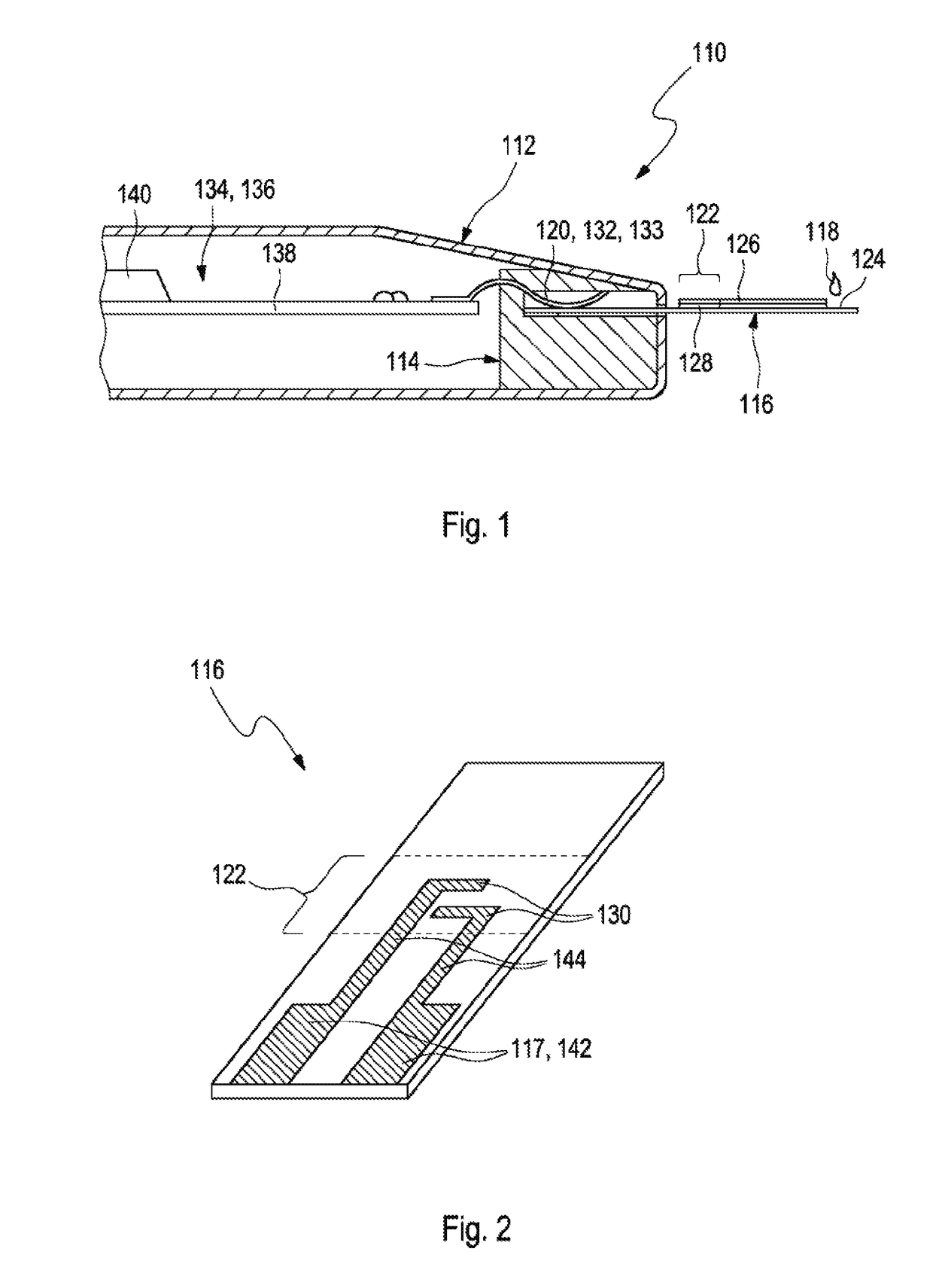
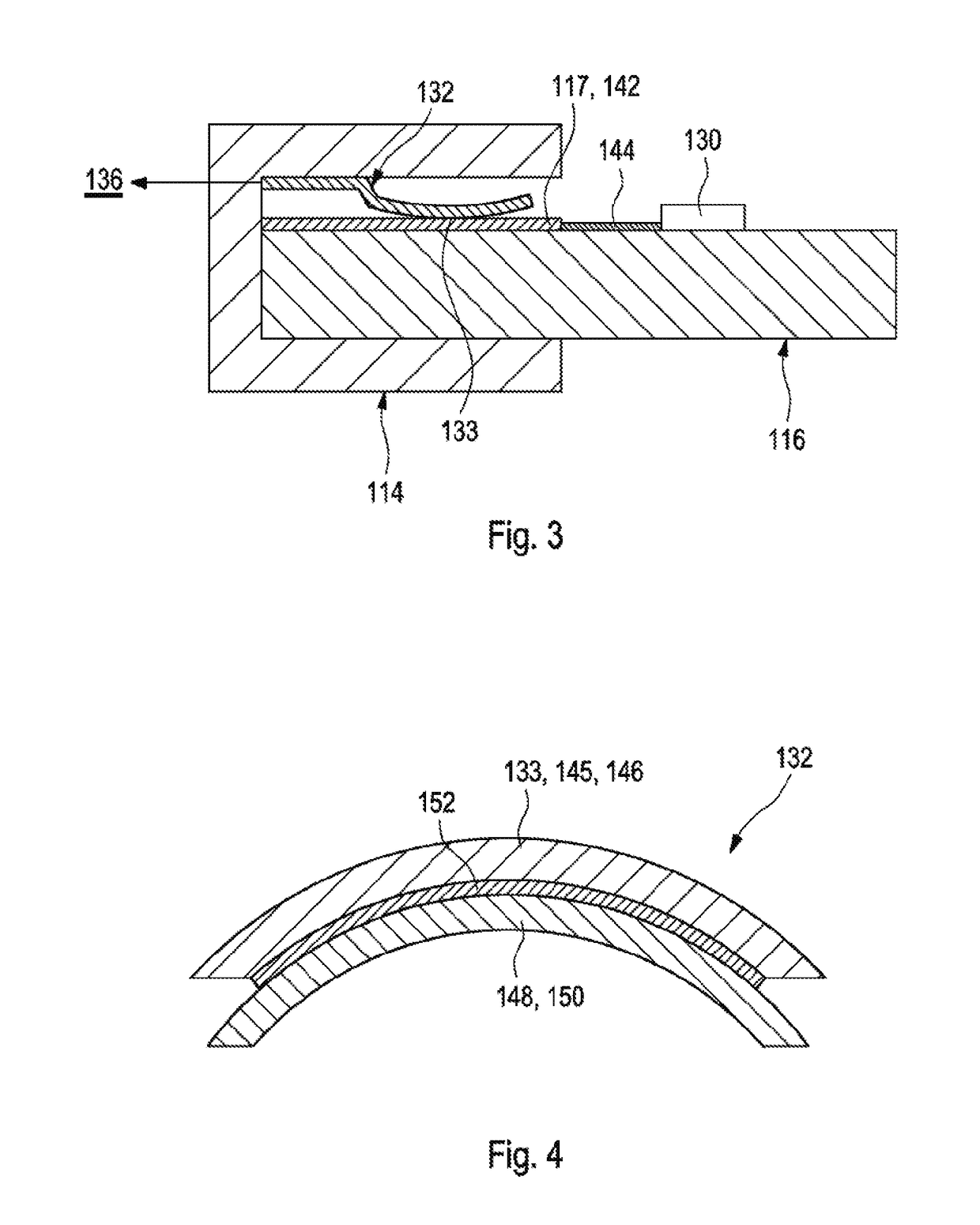
[0028]In the present disclosure, a test element analysis system for an analytical examination of a sample, in particular of a body fluid, is disclosed. The test element analysis system comprises an evaluation device with a test element holder for positioning a test element containing the sample and a measuring device for measuring a change in a measuring zone of the test element. The change is characteristic for an analyte. The test element holder contains contact elements with contact surfaces which allow an electrical contact between contact surfaces of the test element and the contact surfaces of the test element holder. The contact surfaces of the contact elements of the test element holder are provided with an electrically conductive surface containing metallic ruthenium.

[0029]As generally used within the present disclosure, the term “test element analysis system” may refer to an arbitrary device configured for an analytical examination of a sample. The test element analysis sy...

embodiment 1

[0047] Test element analysis system for an analytical examination of a sample, in particular of a body fluid, comprising

[0048]an evaluation device with a test element holder for positioning a test element containing the sample and a measuring device for measuring a change in a measuring zone of the test element, the change being characteristic for an analyte, wherein the test element holder contains contact elements with contact surfaces which allow an electrical contact between contact surfaces of the test element and the contact surfaces of the test element holder,

[0049]wherein the contact surfaces of the contact elements of the test element holder are provided with an electrically conductive surface containing metallic ruthenium.

embodiment 2

[0050] The test element analysis system according to the preceding embodiment, wherein the electrically conductive surface contains pure metallic ruthenium or a compound comprising metallic ruthenium.


PUM


Abstract

A test element analysis system for an analytical examination of a sample, in particular of a body fluid, is disclosed. The test element analysis system comprises an evaluation device with a test element holder for positioning a test element containing the sample and a measuring device for measuring a change in a measuring zone of the test element, the change being characteristic for an analyte. The test element holder contains contact elements with contact surfaces which allow an electrical contact between contact surfaces of the test element and the contact surfaces of the test element holder. The contact surfaces of the contact elements of the test element holder are provided with an electrically conductive surface containing metallic ruthenium.

Description

CROSS-REFERENCE TO RELATED APPLICATIONS[0001]This application is a continuation of International Patent Application No. PCT / EP2017 / 055298, filed 7 Mar. 2017, which claims the benefit of European Patent Application No. 16159142.5, filed 8 Mar. 2016, the disclosures of which are hereby incorporated by reference in their entirety.TECHNICAL FIELD[0002]The present disclosure relates to a test element analysis system for the analytical examination of a sample and, in particular, a body fluid of humans or animals, and a method for manufacturing a test element analysis system.BACKGROUND[0003]Test element analysis systems are commonly used especially in medical diagnostics for analyzing body fluids such as blood or urine. The sample to be examined is firstly applied to a test element. Here the process steps that are required to detect the analyte which are usually chemical, biochemical, biological or immunological detection reactions or physical interactions take place which result in a char...

Claims


Application Information

Patent Timeline
IPC IPC(8): G01N33/487G01N27/327A61B5/145A61B5/1477
CPCG01N33/4875G01N27/3273A61B5/14532A61B5/1477A61B2562/0295
Inventor HEBESTREIT, KAISAECKER, SYLVIATHOME, KLAUSHEIDT, WERNER
Owner ROCHE DIAGNOSTICS OPERATIONS
Learn More