
A multiple output boost dc-dc power converter

a power converter and boost technology, applied in the direction of electric variable regulation, process and machine control, instruments, etc., can solve the problems of more complex circuitry, unsuitable residential or industrial use of sunlight and wind energy, etc., and achieve the effect of reducing component count, high efficiency and simplifying the overall power inverter circuitry

Active Publication Date: 2017-11-16
INFINEON TECH AUSTRIA AG
View PDF5 Cites 26 Cited by
  • Summary
  • Abstract
  • Description
  • Claims
  • Application Information

AI Technical Summary

Benefits of technology

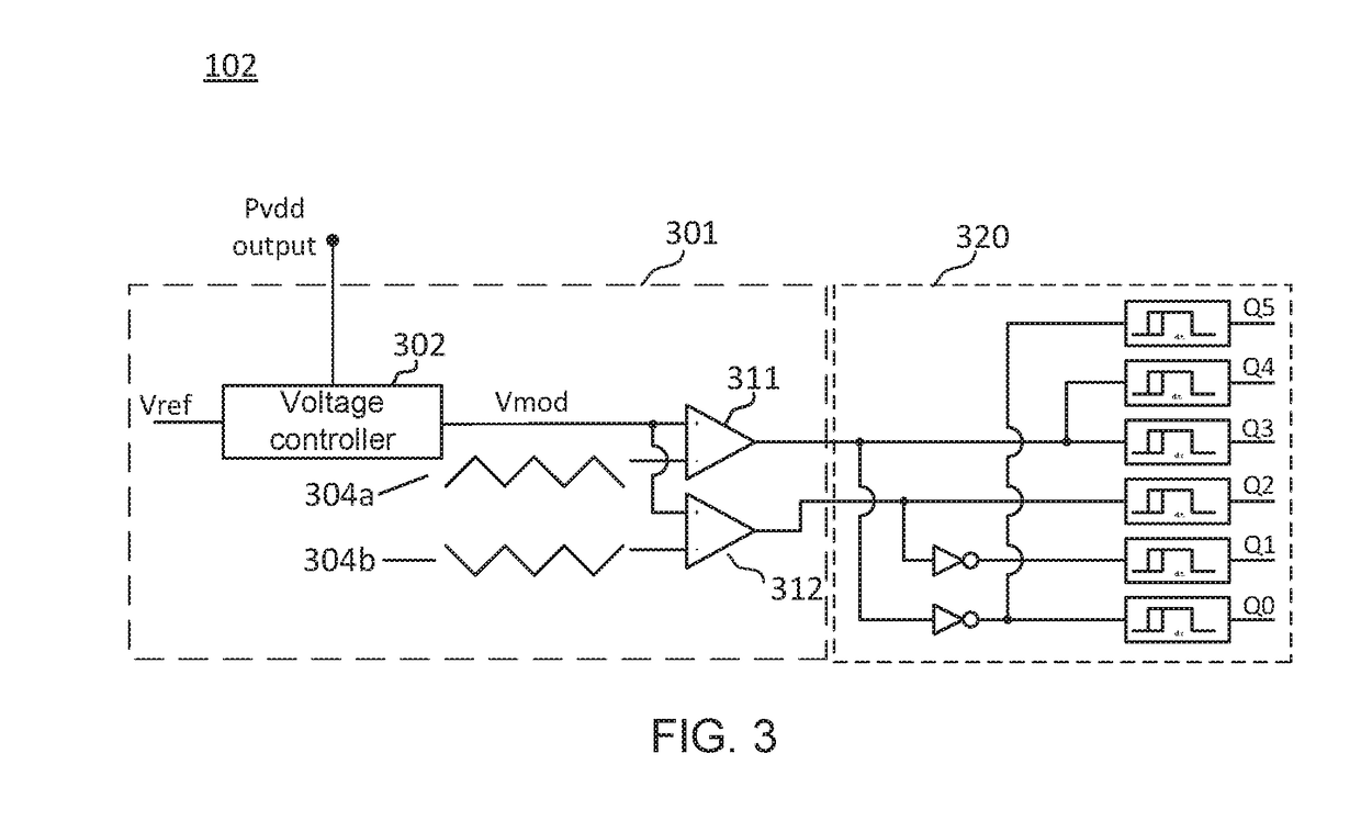
The present invention provides a highly efficient multiple output boost DC-DC power converter with lower component count compared to prior art multiple output DC-DC power converters. This makes it suitable for use in multi-level inverters and simplifies overall power inverter circuitry. Additionally, the invention includes a voltage regulation loop to more accurately control the DC voltage levels despite load variations and variations in the voltage of the DC input voltage supply. This loop can minimize the difference between the target DC voltage and the signal representing one of the first, second, or third DC output voltage.

Problems solved by technology

Energy extracted from energy sources such as sunlight and wind is not usually suitable for use in residential or industrial settings since most electrical equipment requires both relatively stable voltage amplitude, e.g. 120 V or 230 V, and a relatively stable frequency, e.g. 50 Hz or 60 Hz.
However, this type of inverters require three voltage levels, which in itself leads to more complex circuitry than two-level inverters.

Method used


Image

  • A multiple output boost dc-dc power converter
  • A multiple output boost dc-dc power converter
  • A multiple output boost dc-dc power converter

Examples


Embodiment Construction

[0078]In the following, embodiments of the invention will be described with reference to the accompanying drawings. The description and drawings are for illustrative purposes, and the particular embodiments discussed below shall not be considered as limiting the scope of the patent claims.

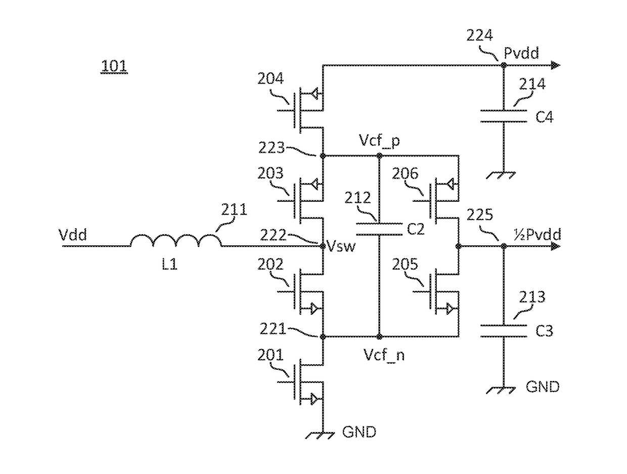
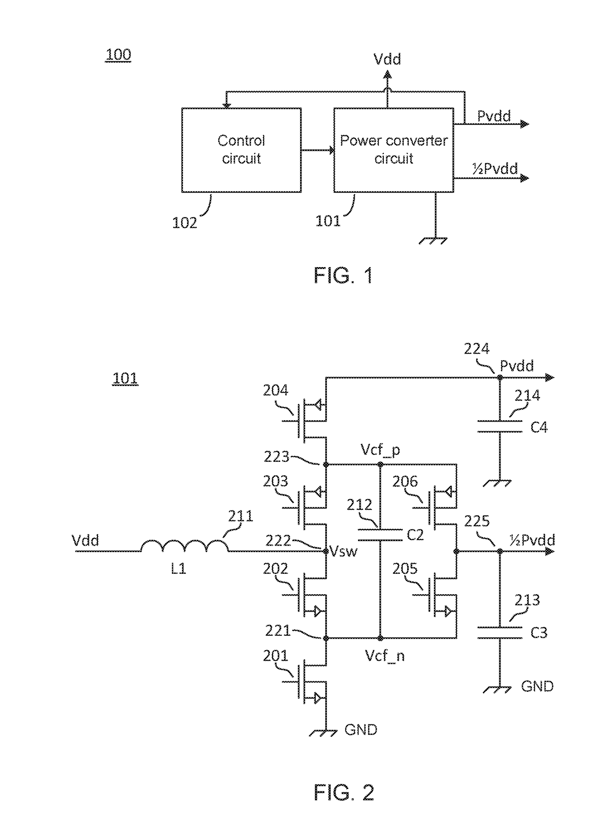
[0079]FIG. 1 illustrates an embodiment of a dual-output boost DC-DC power converter 100 in accordance with a first embodiment of the invention. The dual-output boost DC-DC power converter 100 comprises a power converter circuit 101 and a control circuit 102 for controlling the operation of the DC-DC power converter circuit 101. The power converter circuit 101 is connected to an input power or input voltage supply Vdd which supply energy for the dual-output boost DC-DC power converter 100. The DC-DC power converter 100 is configured to generate separate first and second DC output voltages of different DC levels, Pvdd and ½Pvdd, respectively. The voltage level of the second DC output voltage is appro...


PUM


Abstract

The present invention relates to a multiple output boost DC-DC power converter generating two, three or more separate DC output voltages, and to a multi-level power inverter and an alternating current generator both employing the multiple output boost DC-DC power converter.

Description

[0001]The present invention relates to a multiple output boost DC-DC power converter generating two, three or more separate DC output voltages, and to a multi-level power inverter and an alternating current generator both employing the multiple output boost DC-DC power converter.BACKGROUND OF THE INVENTION[0002]Energy extracted from energy sources such as sunlight and wind is not usually suitable for use in residential or industrial settings since most electrical equipment requires both relatively stable voltage amplitude, e.g. 120 V or 230 V, and a relatively stable frequency, e.g. 50 Hz or 60 Hz. However, power derived from sunlight or wind energy sources can be shaped to a stable alternating current (AC) using capacitive elements for smoothing, and power inverters for conversion from direct current / voltage (DC), typically via a battery, to alternating (ac) current / voltage. Other energy sources, such as fuel cells, also require power inverters in order to become suitable for power...

Claims


Application Information

Patent Timeline
IPC IPC(8): H02M3/158H03F3/183H03F3/217H02M1/08H04R3/00H02M7/537H02M1/00
CPCH02M3/158H02M1/08H02M7/537H03F3/217H03F3/183H04R3/00H02M2001/0083H03F2200/03H02M3/07H02M7/487H02M1/009H02M1/0095H02M7/4837H02M1/0083H03F1/0211H03F1/0244H03F3/2171H03F2200/504
Inventor HOYERBY, MIKKEL
Owner INFINEON TECH AUSTRIA AG
Learn More