Calibration-Free Location Determination Using Wireless Communication

a wireless communication and location determination technology, applied in the direction of reradiation, measurement devices, instruments, etc., can solve the problems of high computational complexity, special hardware requirements for and the performance of triangulation techniques based on these attributes is typically very sensitive to multi-path and non-line-of-sight effects

Active Publication Date: 2017-11-23
ARRIS ENTERPRISES LLC
View PDF2 Cites 12 Cited by
  • Summary
  • Abstract
  • Description
  • Claims
  • Application Information

AI Technical Summary

Benefits of technology

[0008]The described embodiments relate to a computer that includes: an interface circuit that communicates with access points via a network, a processor, and memory that stores a program module that is executed by the processor. During operation, the computer receives, from the access points in sub-regions of an environment, received-signal-strength (RSS) values based on wireless communication between the access points and an electronic device in the environment. Then, the computer selects a subset of the RSS values from a subset of the access points, where the subset of the RSS values includes a largest RSS value associated with

Problems solved by technology

However, the performance of triangulation techniques based on these attributes is typically very sensitive to multi-path and non-line-of-sight effects, which are very common in urban and indoor environments.
In addition, these triangulation techniques often have special hardware requirements and high computational complexity.
Consequently, triangulation techniques are often less attractive for practical deployments.
While radio-fingerprinting techniques can solve many of the drawbacks of the triangulation technique, they do present some problems.
One challenge is the laborious calibration.
This calibration often prolongs the deployment process and increases the deployment cost.
Moreover, the radio-fingerprinting techniques are usually sensitive to dev

Method used


Image

  • Calibration-Free Location Determination Using Wireless Communication
  • Calibration-Free Location Determination Using Wireless Communication
  • Calibration-Free Location Determination Using Wireless Communication

Examples


Embodiment Construction

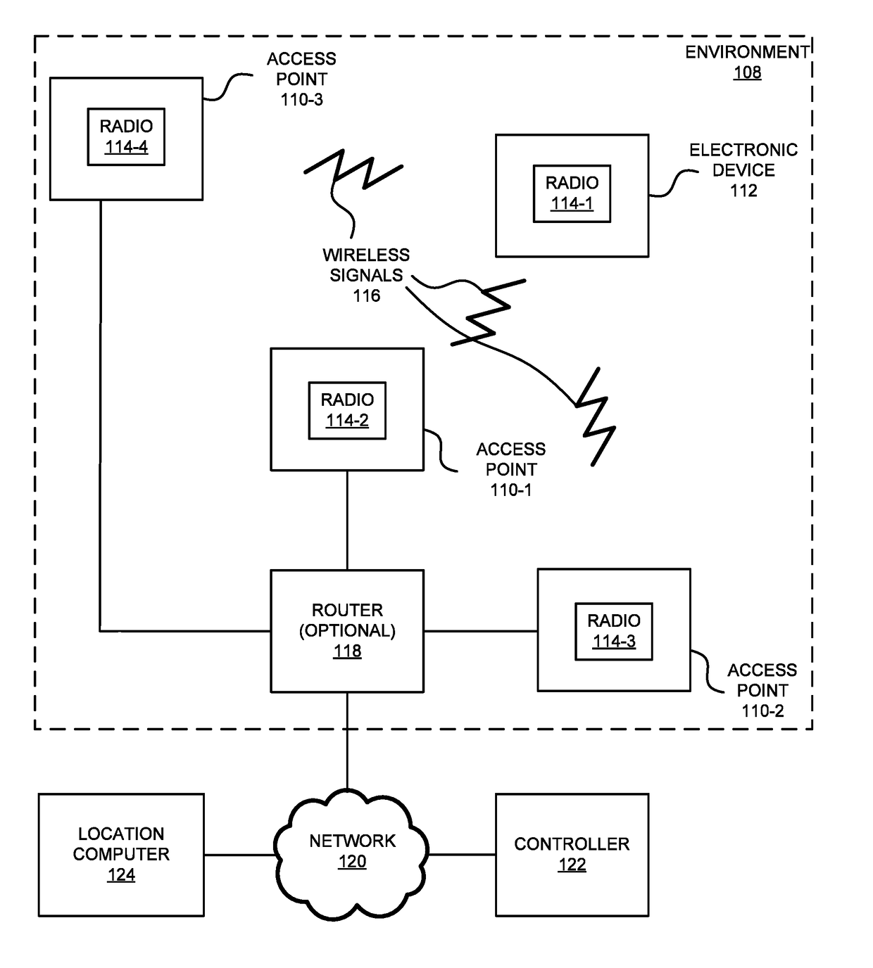
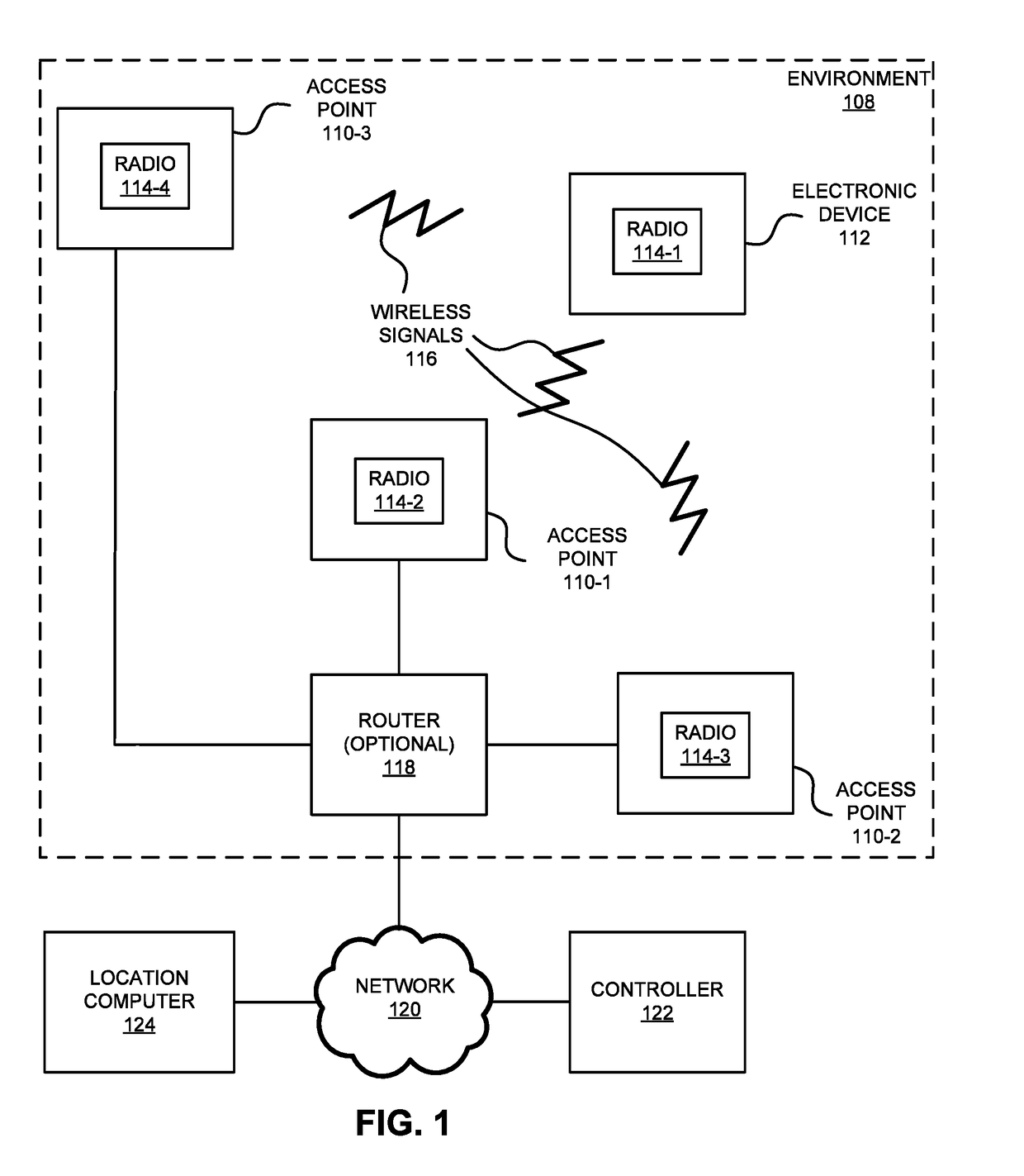
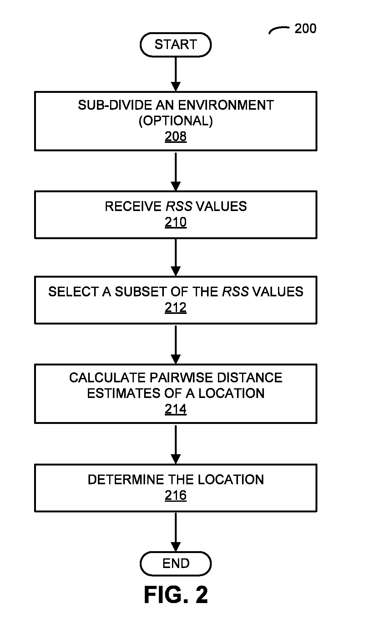
[0031]In order to accurately determine the location of an electronic device in an environment, a computer selects a set of received-signal-strength (RSS) values based on wireless communication between the electronic device and access points in sub-regions of the environment. This set includes a largest RSS value associated with a sub-region and at least two RSS values associated with neighboring sub-regions. Then, the computer calculates pairwise distance estimates of the location of the electronic device in the environment based on predefined locations of the access points associated with the set, one or more differences of pairs of RSS values in the set and a predetermined path-loss factor in the environment, where a given pair of RSS values includes the largest RSS value and one of the at least two RSS values. Furthermore, the computer determines the location of the electronic device in the environment based on the pairwise distance estimates.

[0032]The location-determination tech...


PUM


Abstract

In order to accurately determine the location of an electronic device in an environment, a computer selects a set of received-signal-strength (RSS) values based on wireless communication between the electronic device and access points in sub-regions of the environment. This set includes a largest RSS value associated with a sub-region and at least two RSS values associated with neighboring sub-regions. Then, the computer calculates pairwise distance estimates of the location of the electronic device in the environment based on predefined locations of the access points associated with the set, one or more differences of pairs of RSS values in the set and a predetermined path-loss factor in the environment, where a given pair of RSS values includes the largest RSS value and one of the at least two RSS values. Furthermore, the computer determines the location of the electronic device in the environment based on the pairwise distance estimates.

Description

CROSS REFERENCE TO RELATED APPLICATIONS[0001]This application is a continuation of International Application No. PCT / US2014 / 070015, “Calibration-Free Location Determination Using Wireless Communication,” by Yang Han, filed on Dec. 12, 2014, the contents of which are herein incorporated by reference.BACKGROUNDField[0002]The described embodiments relate to techniques for determining the location of an electronic device. In particular, the described embodiments relate to techniques for determining the location of an electronic device based on wireless communication between a location system and the electronic device without having to calibrate the location system.Related Art[0003]Many electronic devices are capable of wirelessly communicating with other electronic devices. For example, these electronic devices can include a networking subsystem that implements a network interface for: a cellular network (UMTS, LTE, etc.), a wireless local area network (e.g., a wireless network such as ...

Claims


Application Information

Patent Timeline
IPC IPC(8): G01S5/14G01S11/06
CPCG01S11/06G01S5/14G01S5/30
Inventor HAN, YANG
Owner ARRIS ENTERPRISES LLC
Why Eureka
Try Eureka