Detection device and detection method

a detection device and detection method technology, applied in traffic control systems, using reradiation, instruments, etc., can solve the problems of narrow intersections between the stripes of the crosswalks present in the right-turn and left-turn directions, and achieve the effect of short time and avoiding an increase in the load of signal processing

Active Publication Date: 2017-11-23
PANASONIC INTELLECTUAL PROPERTY MANAGEMENT CO LTD
View PDF0 Cites 5 Cited by
  • Summary
  • Abstract
  • Description
  • Claims
  • Application Information

AI Technical Summary

Benefits of technology

[0007]One non-limiting and exemplary embodiment facilitates providing a detection device and a detection method t

Problems solved by technology

However, in the techniques disclosed in Japanese Unexamined Patent Application Publication No. 2013-186663, when the vehicle that enters an intersection photographs the crosswalks that are present in

Method used


Image

  • Detection device and detection method
  • Detection device and detection method
  • Detection device and detection method

Examples


embodiment

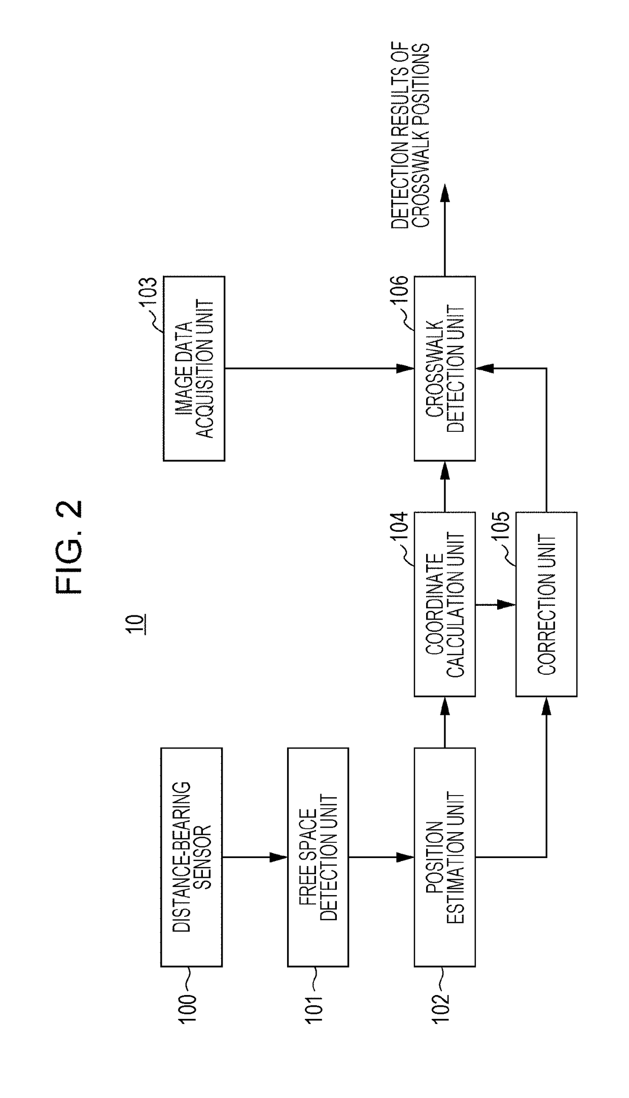
[0028]FIG. 2 is a block diagram that illustrates one example of a configuration of a detection device 10 according to this embodiment. The detection device 10 is installed in a vehicle and detects a crosswalk that is present around the vehicle (for example, in the movement direction of the vehicle such as a front or a lateral side). As illustrated in FIG. 2, the detection device 10 has a distance-bearing sensor 100, a free space detection unit 101, a position estimation unit 102, an image data acquisition unit 103, a coordinate calculation unit 104, a correction unit 105, and a crosswalk detection unit 106.

[0029]The distance-bearing sensor 100 transmits an electromagnetic wave in each bearing of the vehicle and receives the electromagnetic wave that is reflected from an object which is present around the vehicle as a reflected wave. Then, the distance-bearing sensor 100 detects a reflection point based on the reflected wave that is received and generates reflection point information...


PUM


Abstract

There is provided a detection device that includes: a position estimator that estimates a candidate position of a crosswalk in a movement direction of a vehicle and estimates a length of the crosswalk and an intersecting angle between the crosswalk and a roadway using the candidate position; a corrector that corrects the numbers of periods and widths of two basis functions based on the estimated length of the crosswalk and the estimated intersecting angle, the two basis functions corresponding to intervals of white lines of the crosswalk and are orthogonal to each other; and a crosswalk detector that detects whether or not the crosswalk is present using both image data which include the candidate position and the two corrected basis functions.

Description

BACKGROUND1. Technical Field[0001]The present disclosure relates to a detection device that is to be installed in a vehicle and a detection method for detecting a crosswalk on a road surface on which a vehicle travels.2. Description of the Related Art[0002]In recent years, there has been an automatic braking system that detects an object (for example, a vehicle or a pedestrian) around a vehicle by using a camera, a sonar, a radar (for example, a millimeter-wave radar), and so forth and thereby decelerates the vehicle in order to avoid a collision with the object. Further, there has been a warning system that detects an object around the vehicle and thereby notifies a driver of a possibility of a collision with an object. Those systems contribute to prevention of accidents of vehicles.[0003]Those system limit operational conditions of the systems by using various sensors in order to reduce malfunctioning and to improve performance.[0004]For example, performance of the system may be i...

Claims


Application Information

Patent Timeline
IPC IPC(8): G06K9/00G01S13/04G01S13/93G01S13/931G08G1/16
CPCG06K9/00791G08G1/166G01S13/04G01S13/931G06V20/588G01S2013/93271G06V20/56
Inventor MAEDA, MASAKATSUNISHIMURA, HIROFUMISHIMA, TAKAHIROYOSOKU, NAOYAHIRAI, YOSHITO
Owner PANASONIC INTELLECTUAL PROPERTY MANAGEMENT CO LTD
Why Eureka
Try Eureka