Electrically adjustable table system and method for producing an electrically adjustable table system

a technology of electrical adjustment and table system, which is applied in the field of electric adjustable table system, can solve the problems of increasing mounting effort, unnecessary cables and thus resources in conventional cabling

Active Publication Date: 2017-11-30
LOGICDATA ELECTRONICS & SOFTWARE ENTWICKLUNGS
View PDF0 Cites 2 Cited by
  • Summary
  • Abstract
  • Description
  • Claims
  • Application Information

AI Technical Summary

Benefits of technology

[0003]The present disclosure provides an improved cabling concept for electrically adjustable table systems, which can be implemented in a more efficient manner.
[0004]The idea underlying the improved cabling concept is the use of individual, preferably multiwire (German “mehradrig”, English also “multicore”) cable sections for components in a table systems instead of preassembled cables, these cables sections connected to one another via insulation displacement technology, in particular insulation displacement connectors, in particular in a bus system. As a result, the cable amounts required for the table system can be optimized. On the one hand, this results in less cables being used for the cabling. Furthermore, excessive cable amounts need no longer be stored or wound-up or rolled under the table, since the cable length can be adapted to the table dimensions in an optimum manner.
[0006]The ribbon cables can also be formed with an asymmetric profile cross-section, which is adapted to a shape of the insulation displacement connectors. An unambiguous connection or circuiting can be ensured thereby, so that undesired electrical connections can be prevented. For example, this takes effect as a protection against pole reversal.
[0013]In various embodiments, at least some of the cable sections are formed as ribbon cables. At least one of the cable sections formed as a ribbon cable is fixed to the table, e.g. the table frame or the table top, using an adhesive material. The rectangular or substantially rectangular structure of the ribbon cables allows for a stable fixation to be achieved in a simple and reliable manner. This is particularly true when a surface of the ribbon cable along the parallel wires has a smooth or substantially smooth design.
[0024]For example, the second base part is mechanically fixable on the first base part so that the electric connection is reliably maintained. For example, the mechanical connection can be realized via a snap-fit connection or the like. In order to be able to provide the force required for the displacement connectors to penetrate the wires of the cable sections, in some embodiments of the insulation displacement connector, a corresponding lever arrangement is provided, which allows a manual closing of the insulation displacement connector with little effort by lever transmission. Thus, the use of tools such as tongs can be dispensed with.
[0025]In some embodiments, at least one of the insulation displacement connectors is free from an end stop for cable sections to be connected. Accordingly, at least one of the cable sections may run through the insulation displacement connector. This allows for a variable positioning of the insulation displacement connector on the cable section, which is particularly advantageous in longer cable sections. For example, one of the components to be connected can be connected with its respective cable section to the remaining bus system in a flexible manner.

Problems solved by technology

Besides an increased mounting effort, unnecessary cables and thus resources are used in conventional cabling.

Method used


Image

  • Electrically adjustable table system and method for producing an electrically adjustable table system
  • Electrically adjustable table system and method for producing an electrically adjustable table system
  • Electrically adjustable table system and method for producing an electrically adjustable table system

Examples


Embodiment Construction

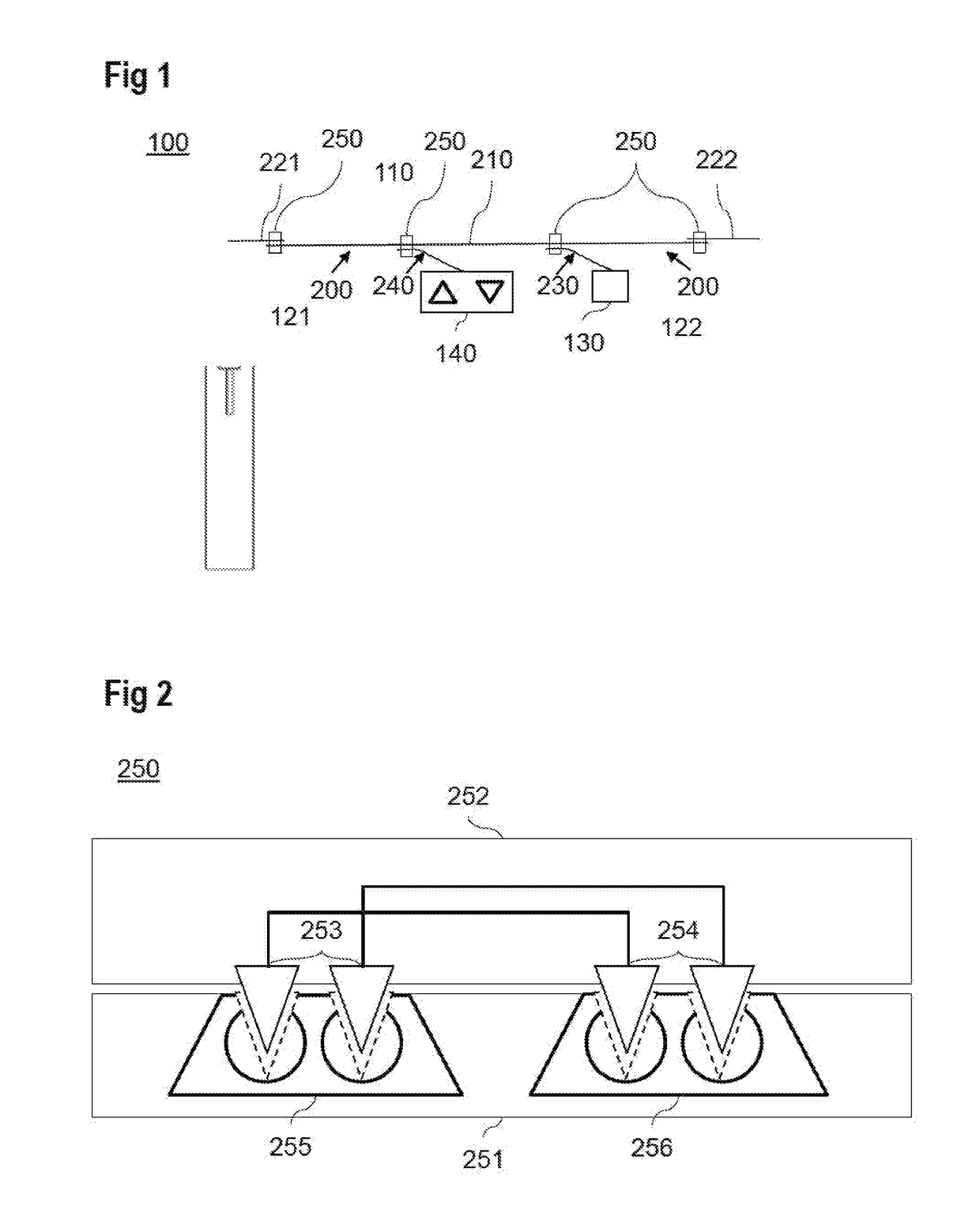
[0034]FIG. 1 shows an embodiment of an electrically adjustable table system having a table 100, which comprises a height-adjustable table top 110, for example. An electric drive 121, 122 is provided in each of the, for example two, illustrated table legs. Furthermore, the table comprises a voltage supply 130 and a control 140. Furthermore, the electrically adjustable table system includes a bus system 200, to which the two drives 121, 122, the voltage supply 130 and the control 140 are connected.

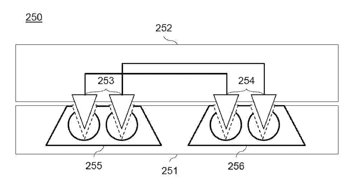
[0035]The bus system 200 is formed of multiple cable sections 210, 221, 222, 230, 240 as well as corresponding bus connectors. These bus connectors are formed as insulation displacement connectors 250, which electrically connect the in each case multiwire cable sections with one another.

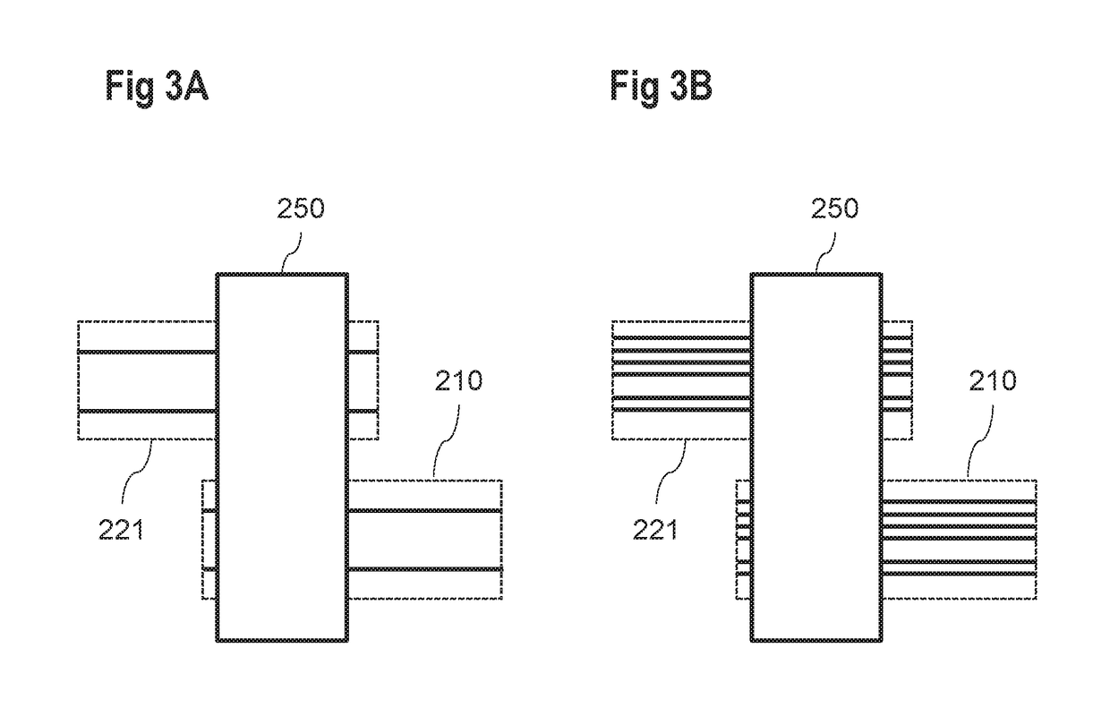
[0036]In various embodiments, at least some of the cable sections 210, 221, 222, 230, 240 are designed as ribbon cables. Incidentally, at least one of the cable sections formed as a ribbon cable is fixed to t...


PUM


Abstract

An electrically adjustable table system includes a table, at least one electric drive for adjusting the table, a voltage supply, a control and a bus system. The at least one drive, the voltage supply and the control are connected to the bus system. The bus system comprises multiple multiwire cable sections, which are electrically connected to one another via insulation displacement connectors.

Description

BACKGROUND OF THE INVENTION[0001]The present disclosure relates to an electrically adjustable table system as well as to a method for producing such a table system.[0002]Electrically adjustable table systems usually include a table, one or multiple electric drives and corresponding control electronics for controlling the drives. The individual components of the table system can be connected to one another via an electric bus system in order to transmit supply voltages and control signals. Usually, for cabling of the components, cables which are fixedly connected to the components are provided, the cables interconnected via plug connectors. As an alternative, preassembled cables of fixed length are used. These cables are adapted to the largest possible dimension of the table. Thus, in smaller tables, parts of the cable must be stored in or under the table, e.g. by rolling or winding. Besides an increased mounting effort, unnecessary cables and thus resources are used in conventional ...

Claims


Application Information

Patent Timeline
Patent Type & Authority Applications(United States)
IPC IPC(8): A47B9/00H01R12/61H01R12/67H02K11/00H01R43/01
CPCA47B9/00H02K11/0094A47B2200/0061H01R12/675H01R43/01H01R12/616A47B2200/0058A47B2200/0059
Inventor KOCH, WALTER
Owner LOGICDATA ELECTRONICS & SOFTWARE ENTWICKLUNGS
Why Eureka
Try Eureka